| CPC F01D 17/02 (2013.01) [F01D 9/041 (2013.01); F05D 2220/323 (2013.01); F05D 2240/12 (2013.01); F05D 2260/80 (2013.01)] | 19 Claims |

|
1. A gas turbine engine comprising:
a high pressure turbine; a low pressure turbine positioned downstream of the high pressure turbine; and
an inter-turbine duct positioned between the high pressure turbine and the low pressure turbine, the inter-turbine duct defining an axial direction, a radial direction, and a circumferential direction, the inter-turbine duct comprising:
an inner annular wall;
an outer annular wall spaced apart from the inner annular wall along the radial direction to define an annular flow passage;
a plurality of circumferentially spaced vanes positioned within the flow passage and extending between the inner annular wall and the outer annular wall, each of the vanes is a stationary guide vane defining a leading edge, a circumferential distance being defined between the leading edges of adjacent vanes that increases in a circumferential direction that extends from a suction side of a first one of the adjacent vanes to a pressure side of a second one of the adjacent vanes; and
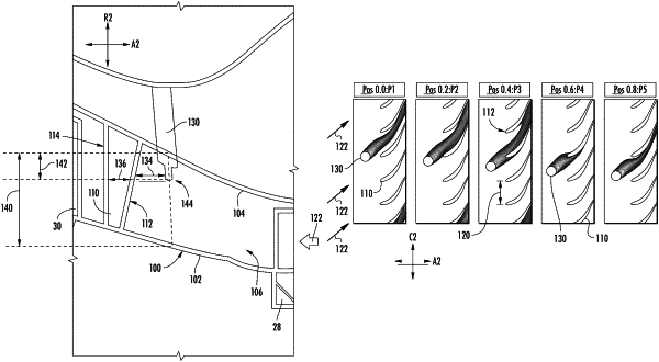
a probe positioned within the flow passage and extending substantially along the radial direction, the probe being positioned upstream from the vanes along the axial direction such that an axial gap is defined between the probe and the leading edge of a respective vane along the axial direction, the axial gap being greater than one quarter of an axial length of the respective vane measured along the axial direction, the probe being further positioned at a circumferential location that is between thirty and seventy percent of the circumferential distance between the leading edges of adjacent vanes, the probe configured to measure an operating characteristic of the gas turbine engine.
|