| CPC B60H 1/3227 (2013.01) [B60K 11/04 (2013.01); F01P 3/18 (2013.01); F25B 39/04 (2013.01); F28D 1/0435 (2013.01); F28F 9/002 (2013.01); F28F 9/013 (2013.01); F28F 9/02 (2013.01); F28F 9/262 (2013.01); F28F 2255/143 (2013.01)] | 14 Claims |
|
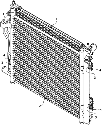
1. A cooling module comprising:
a radiator comprising:
first and second header tanks disposed to face each other; and
hook parts respectively disposed at upper and lower sides of the first header tank and a lower side of the second header tank; and
a condenser comprising:
third and fourth header tanks disposed to face each other;
a flange connection part coupled to the third header tank; and
a gas-liquid separator coupled to the fourth header tank,
wherein the condenser is coupled to the radiator as the flange connection part, the third header tank, and the gas-liquid separator are inserted into the plurality of the hook parts, respectively, in a direction from an upper side to a lower side thereof,
wherein the plurality of the hook parts comprises:
a first hook part disposed at the upper side of the first header tank; and
a third hook part disposed at the lower side of the second header tank,
wherein the first hook part comprises:
a first horizontal portion protruding from an outer circumferential surface of the first header tank; and
a first vertical portion extending from an end of the first horizontal portion in an upward direction, and
wherein the flange connection part is inserted into a space between the first header tank and the first vertical portion,
wherein the first hook part comprises a first-1 stopper protruding from an end of the first vertical portion toward the first header tank, and the first-1 stopper has an inclined portion provided at an upper end of an inner surface thereof,
wherein the forward and rearward motions of the flange connection part are restricted by the first vertical portion, the upward and downward motions of the flange connection part are restricted by the first-1 stopper.
|