| CPC B60H 1/00921 (2013.01) [B60H 1/00392 (2013.01); B60H 1/22 (2013.01); B60H 1/3213 (2013.01); F25B 5/02 (2013.01); F25B 6/04 (2013.01); F25B 13/00 (2013.01); F25B 40/00 (2013.01); F25B 41/20 (2021.01); F25B 41/30 (2021.01); F25B 41/42 (2021.01); B60H 2001/00928 (2013.01); B60H 2001/00935 (2013.01); B60H 2001/00957 (2013.01); B60H 2001/3291 (2013.01); F25B 2600/2507 (2013.01); F25B 2600/2513 (2013.01); F25B 2600/2515 (2013.01); F25B 2700/1933 (2013.01); F25B 2700/21151 (2013.01)] | 12 Claims |
|
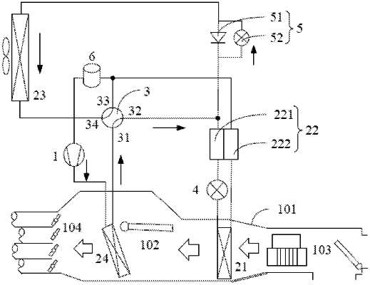
1. A heat pump system, comprising: a compressor, a first heat exchanger, a second heat exchanger, a third heat exchanger, a fourth heat exchanger, a flow regulating valve assembly, a fluid switching valve and a refrigerant throttling and depressurizing valve;
the second heat exchanger comprising a first heat exchange portion and a second heat exchange portion which are capable of exchanging heat with each other, the refrigerant throttling and depressurizing valve being connected between an outlet of the first heat exchange portion and an inlet of the first heat exchanger, an inlet of the first heat exchange portion being capable of communicating with at least one of a second port of the third heat exchanger and an outlet of the fourth heat exchanger, and the flow regulating valve assembly being connected between the second port of the third heat exchanger and the inlet of the first heat exchange portion;
the fluid switching valve having a first port, a second port, a third port and a fourth port, wherein the first port of the fluid switching valve is capable of communicating with the outlet of the compressor or the outlet of the fourth heat exchanger, the second port of the fluid switching valve is capable of communicating with the inlet of the first heat exchange portion and/or the flow regulating valve assembly, the third port of the fluid switching valve is capable of communicating with the outlet of the second heat exchange portion and/or the inlet of the compressor, and the fourth port of the fluid switching valve is capable of communicating with the first port of the third heat exchanger;
a first port of the third heat exchanger being capable of communicating with an inlet of the compressor, and the outlet of the fourth heat exchanger being capable of communicating with the second port of the third heat exchanger through the flow regulating valve assembly; or, the first port of the third heat exchanger communicating with the outlet of the fourth heat exchanger, and the fourth heat exchanger being capable of communicating with the flow regulating valve assembly through the third heat exchanger;
an inlet of the second heat exchange portion communicating with an outlet of the first heat exchanger, and an outlet of the second heat exchange portion being capable of communicating with the inlet of the compressor;
the heat pump system comprising a heating mode in which the first port of the third heat exchanger is in communication with the inlet of the compressor, an outlet of the compressor is in communication with an inlet of the fourth heat exchanger, the outlet of the fourth heat exchanger is in communication with the second port of the third heat exchanger through the flow regulating valve assembly, the refrigerant throttling and depressurizing valve is closed, and the flow regulating valve assembly throttles and depressurizes a refrigerant;
the heat pump system comprises a cooling mode in which the outlet of the compressor, the fourth heat exchanger, the first port of the fluid switching valve, the fourth port of the fluid switching valve, the third heat exchanger, the flow regulating valve assembly, the first heat exchange portion, the refrigerant throttling and depressurizing valve, the first heat exchanger, the second heat exchange portion, and the inlet of the compressor are communicated in sequence;
the heat pump system further comprises a refrigerant flowing control branch connected to the second heat exchanger, and the refrigerant flowing control branch is used to control flow of the refrigerant flowing through the second heat exchanger in the cooling mode;
wherein the refrigerant flowing control branch comprises a first branch connected in parallel with the first heat exchange portion and a first flow regulating valve disposed at the first branch, the first branch has a first connection position connected to an inlet side of the first heat exchange portion and a second connection position connected to an outlet side of the first heat exchange portion, the second connection position is located between the first heat exchange portion and the refrigerant throttling and depressurizing valve; when the heat pump system operates under the cooling mode, at least part of the refrigerant flows through the first heat exchange portion, and the first flow regulating valve is configured for controlling the flow of the refrigerant flowing through the first heat exchange portion and the first branch; or
the refrigerant flowing control branch comprises a second branch connected in parallel with the second heat exchange portion and a second flow regulating valve disposed at the second branch, the second branch has a third connection position connected to an inlet side of the second heat exchange portion and a fourth connection position connected to an outlet side of the second heat exchange portion, the third connection position is located between the inlet side of the second heat exchange portion and an outlet side of the first heat exchanger; when the heat pump system operates under the cooling mode, at least part of the refrigerant flows through the second heat exchange portion, and the second flow regulating valve is configured for controlling the flow of the refrigerant flowing through the second heat exchange portion and the second branch.
|