| CPC B60G 17/0162 (2013.01) [B60G 13/08 (2013.01); B60G 17/08 (2013.01); B60G 2202/24 (2013.01); B60G 2202/413 (2013.01); B60G 2400/0521 (2013.01); B60G 2400/0522 (2013.01); B60G 2400/0523 (2013.01); B60G 2400/053 (2013.01); B60G 2400/10 (2013.01); B60G 2400/204 (2013.01); B60G 2400/41 (2013.01)] | 18 Claims |

|
1. A vehicle comprising:
a suspension system comprising:
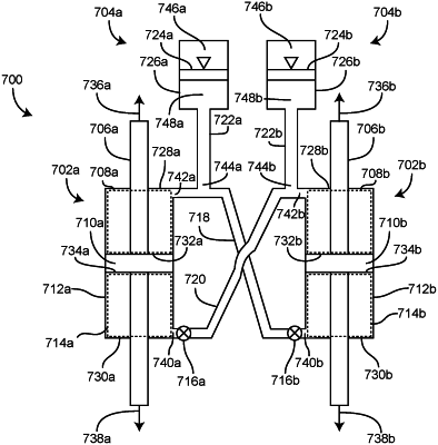
a first damper and a second damper, the first damper and the second damper configured to control at least one of a roll or pitch of the vehicle, wherein each of the first damper and the second damper comprise a piston configured to divide each damper into a first chamber and a second chamber; and
an accumulator fluid circuit including a variable relief valve, a pressure compensated valve, and a one-way valve, the accumulator fluid circuit configured to control fluid entering or exiting at least one of the first chamber or the second chamber of at least one of the first damper or the second damper;
wherein the first damper is fluidly connected to the second damper by a first hydraulic line connecting the first chamber of the first damper to the second chamber of the second damper and a second hydraulic line connecting the second chamber of the first damper to the first chamber of the second damper, wherein at least one of the variable relief valve, the pressure compensated valve, or the one-way valve is positioned in line with at least one of the first hydraulic line or the second hydraulic line.
|