| CPC B41J 2/17523 (2013.01) [B41J 2/17513 (2013.01); B41J 2/17526 (2013.01); B41J 2/17553 (2013.01); B41J 29/02 (2013.01); B41J 29/13 (2013.01)] | 6 Claims |
|
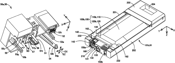
1. A combination of a liquid container and case configured to be mounted to and removed from a liquid ejection apparatus including, when directions parallel to a gravity direction are Z directions, a direction of the Z directions which is the same as the gravity direction is a +Z direction, a direction of the Z directions opposite to the gravity direction is a −Z direction, directions intersecting the Z directions are Y directions, one direction of the Y directions is a +Y direction and another direction of the Y directions is a −Y direction, directions orthogonal to the Z directions and the Y directions are X directions, one direction of the X directions is a +X direction and another direction of the X directions is a −X direction:
a case storage portion;
an apparatus-side fixing structure positioned on an end of the case storage portion on the +Y direction side;
a liquid introduction portion positioned on the end of the case storage portion on the +Y direction side; and
an apparatus-side electrical connection unit positioned on the end of the case storage portion on the +Y direction side, the combination of the liquid container and case comprising:
a case configured to move along the +Y direction to thereby be inserted into the case storage portion; the case including:
a case-side fixing structure including a loop-shaped groove portion and an engaging portion which is provided in the groove portion and locks the apparatus-side fixing structure; and
a liquid container configured to be mounted to and removed from the case, the liquid container including:
a storage portion configured to store liquid; and
a connection member positioned on an end on the +Y direction side when the liquid container is in a mounting state in which the liquid container is mounted to the liquid ejection apparatus,
wherein the connection member is provided with:
a liquid outlet configured to receive insertion of the liquid introduction portion in the +Y direction in the mounting state; and
a container-side electrical connector configured to electrically connect to the apparatus-side electrical connection unit, the container-side electrical connector including a contact surface, a normal vector of which includes a −Z direction vector component and a +Y direction vector component in the mounting state,
wherein the case-side fixing structure and the container-side electrical connector are provided at positions at which the case-side fixing structure and the container-side electrical connector at least partially overlap when viewed from the Z directions in a posture in the mounting state,
wherein, in the posture in the mounting state, a width of the liquid container in the Z directions is smaller than a width of the liquid container in the Y directions and a width of the liquid container in the X directions, and
wherein, in a state that the container-side fixing structure engages with the case-side fixing structure, the engaging portion restricts movement of the combination of the liquid container and case toward the −Y direction and the container-side electric connector electrically connects to the apparatus-side electrical connection unit while a force facing the −Y direction and the −Z direction is applied to the contact surface.
|