| CPC B29C 45/16 (2013.01) [B29C 45/0001 (2013.01); B29C 45/641 (2013.01); B29C 2045/0094 (2013.01); B29K 2075/00 (2013.01); B29K 2105/0094 (2013.01); B29K 2995/0097 (2013.01); B29L 2011/0016 (2013.01)] | 19 Claims |

|
1. An injection molding apparatus comprising:
a substantially circular first substrate;
a substantially circular second substrate disposed to face a surface of the first substrate;
a fixing member which fixes a peripheral end portion of the first substrate and a peripheral end portion of the second substrate;
a gap formed by entire opposing surfaces of the first substrate and the second substrate;
an injection portion which is provided in the fixing member; and
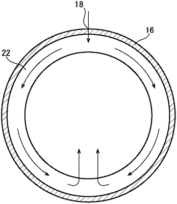
a space connecting with the injection portion and the gap is provided in at least a part of a periphery of the gap;
wherein a width of the space in a thickness direction is larger than a width of the gap in the thickness direction,
the width of the gap in the thickness direction is substantially the same through the entire gap, and
the injection portion injects a composition into the space.
|