| CPC B23C 5/06 (2013.01) [B23C 5/202 (2013.01); B23C 2200/0411 (2013.01); B23C 2200/0483 (2013.01); B23C 2200/125 (2013.01); B23C 2200/20 (2013.01); B23C 2200/28 (2013.01); B23C 2200/365 (2013.01); B23C 2210/50 (2013.01)] | 13 Claims |

|
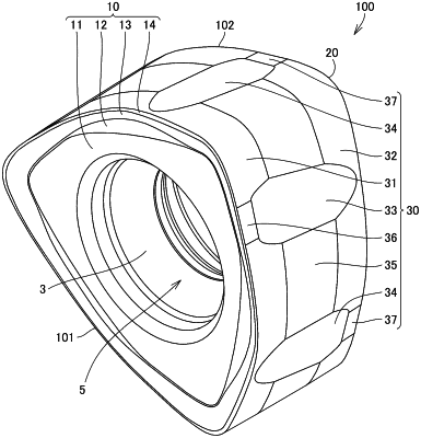
1. A cutting insert for a rotary cutting tool, the cutting insert comprising:
a first surface;
a second surface opposite to the first surface;
an outer circumferential surface which is contiguous to each of the first surface and the second surface; and
an inner circumferential surface which is inside the outer circumferential surface and constitutes a through hole, wherein
a ridgeline between the first surface and the outer circumferential surface includes a first cutting edge,
a ridgeline between the second surface and the outer circumferential surface includes a second cutting edge,
the first surface includes a first seating surface having a shape of a flat surface,
the second surface includes a second seating surface having a shape of a flat surface,
the first cutting edge has a first main cutting edge portion and a first sub cutting edge portion,
the second cutting edge has a second main cutting edge portion and a second sub cutting edge portion,
when viewed in a direction from the first surface toward the second surface, at least a portion of the second sub cutting edge portion is located outside the first main cutting edge portion, and at least a portion of the first sub cutting edge portion is located outside the second main cutting edge portion,
when viewed in the direction from the first surface toward the second surface, each of the first sub cutting edge portion and the second sub cutting edge portion has a shape of a curved line, and
the outer circumferential surface includes a third seating surface having a shape of a flat surface,
in a cross section which is parallel to the direction from the first surface toward the second surface and which intersects the first main cutting edge portion, the third seating surface, and the second sub cutting edge portion, an angle formed between the third seating surface and the first seating surface is an obtuse angle, and an angle formed between the third seating surface and the second seating surface is an acute angle,
the outer circumferential surface includes a flank face which is located between the first main cutting edge portion and the third seating surface, and
the flank face is inclined toward the through hole relative to the third seating surface.
|