| CPC B06B 1/0253 (2013.01) [A61B 17/320068 (2013.01); A61F 9/00745 (2013.01); B06B 1/0246 (2013.01); H03F 1/0216 (2013.01); A61B 2017/00017 (2013.01); A61B 2017/0003 (2013.01); A61B 2017/00199 (2013.01); A61B 2017/00477 (2013.01); A61B 2017/00973 (2013.01); A61B 17/142 (2016.11); A61B 2017/320069 (2017.08); A61B 2017/32007 (2017.08); A61B 2018/00029 (2013.01); A61B 2018/00577 (2013.01); A61B 18/14 (2013.01); A61B 2018/1807 (2013.01); A61B 90/98 (2016.02); A61B 2217/005 (2013.01); A61B 2217/007 (2013.01); B06B 2201/55 (2013.01); B06B 2201/76 (2013.01); H02M 3/158 (2013.01); H03F 3/45475 (2013.01); H03F 2200/541 (2013.01)] | 20 Claims |

|
1. A control console for supplying an AC drive signal to a driver of an ultrasonic handpiece to vibrate a tip of the ultrasonic handpiece, the control console comprising:
a transformer including a primary winding having first and second opposed ends and a center tap to which a DC voltage is applied, and including a secondary winding across which the AC drive signal is developed for vibrating the tip of the ultrasonic handpiece;
first and second transistors functioning as first and second active resistors coupled to the first and second opposed ends of the primary winding respectively for developing an AC voltage across the primary winding;
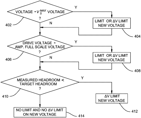
a headroom monitor coupled to the first and second transistors and configured to generate a headroom signal representative of a voltage across the first and second transistors; and
a processor coupled to the headroom monitor and configured to:
adjust a target headroom voltage for the first and second transistors based on a voltage of the AC drive signal; and
regulate the AC voltage developed across the primary winding based on the headroom signal and the adjusted target headroom voltage.
|