| CPC B05B 1/26 (2013.01) [B60S 1/52 (2013.01); B60S 1/56 (2013.01)] | 6 Claims |

|
1. A liquid jetting nozzle comprising:
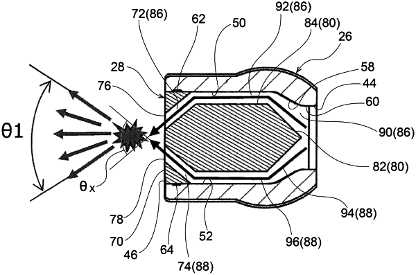
a nozzle main body having a proximal end and a distal end and including, at the proximal end, an introduction port at which a liquid is introduced, and including, at the distal end, an insertion aperture that communicates with a space within the nozzle main body, the space communicating with the introduction port, the space being bounded by a first interior wall, a second interior wall, a third interior wall and a fourth interior wall, the first and second interior walls opposing each other, the third and fourth interior walls opposing each other, the first and second interior walls being orthogonal to the third and fourth interior walls; and
a nozzle tip that is inserted through the insertion aperture of the nozzle main body and positioned within the space of the nozzle main body, the nozzle tip having a first exterior wall, a second exterior wall, a third exterior wall and a fourth exterior wall, the first, second, third and fourth exterior walls being respectively positioned adjacent to the first, second, third and fourth interior walls of the nozzle main body when the nozzle tip is positioned within the space of the nozzle main body, a first channel and a second channel both being formed in one of the first, second, third and fourth exterior walls of the nozzle tip, the first and second channels extending from a proximal end of the nozzle tip to a distal end of the nozzle tip at which a first ejection port and a second ejection port are formed by respective distal ends of the first and second channels, the first ejection port and the second ejection port each jetting out the liquid that has been introduced via the introduction port, wherein:
the first channel includes a first downstream side channel at a downstream side region of the first channel through which the liquid flows from the introduction port toward the distal end of the first channel at which the first ejection port is formed, and the second channel includes a second downstream side channel at a downstream side region of the second channel through which the liquid flows from the introduction port toward the distal end of the second channel at which the second ejection port is formed, and
an angle formed between the first downstream side channel and the second downstream side channel is configured such that the liquid jetted out from the first ejection port and the liquid jetted out from the second ejection port collide.
|