| CPC A63B 53/0466 (2013.01) [A63B 53/04 (2013.01); A63B 60/02 (2015.10); A63B 53/0408 (2020.08); A63B 53/0412 (2020.08); A63B 53/0433 (2020.08); A63B 53/0437 (2020.08); A63B 53/045 (2020.08); A63B 2053/0491 (2013.01); A63B 53/08 (2013.01)] | 20 Claims |

|
1. A method of manufacturing a golf club head, comprising:
providing a body portion having a top portion, a bottom portion, a heel portion, a toe portion, a rear portion, and a front portion;
providing a face portion coupled to the front portion, the face portion comprising:
a front surface;
a rear surface opposite the front surface; and
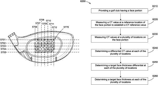
a plurality of square face regions on the rear surface of the face portion, the plurality of square face regions defined by a plurality of vertical lines and a plurality of horizontal lines that intersect the plurality of vertical lines, the plurality of square face regions forming a grid of square face regions comprising a plurality of rows of square face regions and a plurality of columns of square face regions;
determining a reference characteristic time value at a reference location on the face portion, the reference location being located within a sweet spot on the face portion;
determining a measured characteristic time value at each of a plurality of locations on the rear surface of the face portion, the plurality of locations corresponding to intersection points between the plurality of horizontal lines and the plurality of vertical lines;
determining a differential characteristic time value at each of the plurality of locations, each differential characteristic time value being determined by subtracting the reference characteristic time value from the measured characteristic time value; and
altering a face thickness of the face portion at a location where the differential characteristic time value is nonzero,
wherein the square face regions of each row are linearly aligned,
wherein the square face regions of each column are linearly aligned,
wherein each square face region is defined by an intersection of two vertical lines of the plurality of vertical lines and two horizontal lines of the plurality of horizontal lines,
wherein each square face region includes a first corner thickness at an intersection of a first vertical line of the plurality of vertical lines and a first horizontal line of the plurality of horizontal lines,
wherein each square face region includes a second corner thickness at an intersection of a second vertical line of the plurality of vertical lines and the first horizontal line of the plurality of horizontal lines,
wherein each square face region includes a third corner thickness at an intersection of the first vertical line of the plurality of vertical lines and a second horizontal line of the plurality of horizontal lines,
wherein each square face region includes a fourth corner thickness at an intersection of the second vertical line of the plurality of vertical lines and the second horizontal line of the plurality of horizontal lines,
wherein each square face region includes an average thickness determined by summing the corresponding first, second, third, and fourth corner thicknesses and dividing by four, and
wherein two or more of the square face regions have differing average thicknesses.
|