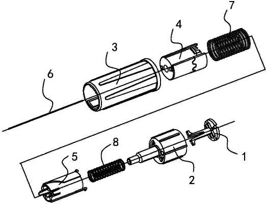
| CPC A61M 5/3202 (2013.01) [A61M 5/3134 (2013.01)] | 8 Claims |

|
1. A safety insulin pen needle comprising:
a needle body with an injection section at a front end of the needle body and a connecting section at a rear end of the needle body;
an intermediate shield that has a tube structure, the intermediate shield being provided with a through hole at a front end of the intermediate shield and being connected to, or provided with a connector configured to connect to, an insulin pen at a rear end of the intermediate shield;
a front shield that protects the injection section of the needle body, a main structure of the front shield being a tubular body;
a tail cover that protects the connecting section of the needle body;
a rear spring that pushes the tail cover to a protection position at which the tail cover protects the connecting section of the needle body; and
a rotating tube, a main structure of the rotating tube being a tubular body, an outer edge of the tubular body of the rotating tube being provided with a beveled rail, the beveled rail being composed of a section of bevel or spiral surface as a guiding surface; wherein:
an inner edge of the front shield is provided with a bevel acting part that interacts with the beveled rail on the rotating tube;
the tail cover is composed of a cap and an elastic leg, the cap is an end cap or a ring body, a center of the cap is provided with a cannula passing hole configured for insertion of the connecting section of the needle body, a rear part of the elastic leg is fixedly connected with the cap, a front of the elastic leg is provided with a rear protection stopper, and a front end face of the rear protection stopper is a front stopping face;
an inner edge of the tubular body of the rotating tube is provided with a first rail slot and a second rail slot that interact with the rear protection stopper on the elastic leg of the tail cover, and the first rail slot and the second rail slot are arranged in parallel along an axial direction of the tubular body of the rotating tube and are spaced apart along a circumferential direction of the tubular body of the rotating tube;
a transverse channel is arranged circumferentially on the inner edge of the tubular body of the rotating tube in front of the first rail slot and the second rail slot;
in an assembly state before use,
the needle body is located in the intermediate shield, and is fixed relative to the intermediate shield;
the rotating tube is located in the intermediate shield, is axially positioned and connected relative to the intermediate shield, and is configured to be circumferentially rotatable;
a rear part of the front shield extends into the intermediate shield and is sleeved outside the rotating tube, a front part of the front shield extends out of the through hole at the front end of the intermediate shield, the front shield and the intermediate shield are slidably connected in the axial direction, and the front shield is provided with a front end limit that limits forward movement of the front shield relative to the intermediate shield;
the bevel acting part on the inner edge of the front shield is located on the beveled rail;
the tail cover is located in the intermediate shield and the connecting section of the needle body is inserted in the cannula passing hole of the cap of the tail cover;
the rear protection stopper of the elastic leg of the tail cover is located in the first rail slot of the rotating tube; and
the rear spring is located in the intermediate shield, a front end of the rear spring is positioned relative to the intermediate shield or the rotating tube, and a rear end of the rear spring pushes against the tail cover; and
in a use state,
when the insulin pen needle is pushed, the front shield moves backward axially relative to the intermediate shield, and the bevel acting part on the inner edge of the front shield and the beveled rail on the outer edge of the rotating tube interact with each other to force the rotating tube to rotate in the circumferential direction relative to the front shield, and the rear protection stopper on the elastic leg of the tail cover slides laterally to the second rail slot along the transverse channel;
when the insulin pen exits the intermediate shield, the rear spring pushes the tail cover to move backward, and at the same time, the rear protection stopper on the elastic leg of the tail cover moves backward along the second rail slot; and
when the rear protection stopper moves backward along the second rail slot to a rear end limit position, the rear protection stopper deflects outward, and at this time, the front stopping face of the rear protection stopper is against a rear end face of the second rail slot, so that the tail cover is axially positioned relative to the intermediate shield and enters a rear-end protection state.
|