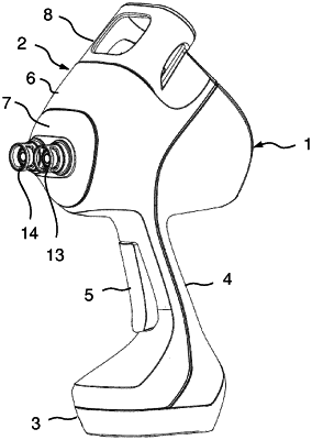
| CPC A61M 5/30 (2013.01) [A61M 2005/3114 (2013.01); A61M 2005/3128 (2013.01); A61M 2250/00 (2013.01)] | 16 Claims |

|
1. A device for administering a fluid, comprising
a cylinder (16, 116) which has an open dispensing end (17),
a piston (36) which is displaceable between a front end position and a rear end position in the cylinder (16, 116) and is connected to a piston rod (35) that protrudes along a first direction beyond a rear end of the cylinder (16, 116) opposite the open dispensing end (17) and is guided in a receiving block (10),
a nonreturn valve (18) closing the open dispensing end (17), and
a tensioning device (S) which is connected to the piston rod (35, 135) and is arranged in the receiving block (10),
wherein the tensioning device (S), when the piston (36) is in the front end position, can move the piston rod (35, 135) in a tensioning operation along the first direction until the piston (36) is in the rear end position in order thereby to fill the cylinder (16, 116) with the fluid to be administered and in order to pretension the piston rod (35, 135) toward the open dispensing end (17), and
wherein the tensioning device (S), when the piston (36) is in the rear end position, can release the piston rod (35, 135) in a dispensing operation, and therefore the piston (36) moves counter to the first direction as far as the front end position because of the applied pretension and, in the process, fluid in the cylinder (16, 116) is dispensed via the nonreturn valve (18) for administering,
the tensioning device (S) has a ramp (52) which is rotatable by means of a motor (12) and has a ramp track (53) extending along a helical line,
wherein the ramp track (53) ascends from a first plateau along a region of inclination (S1, S2) to a second plateau and descends from the second plateau to the first plateau via a transition flank (46),
wherein the tensioning device (S) furthermore has a roller (51) which is in contact with the ramp track (53) and is mounted rotatably in a driver (50), which is connected to the end of the piston rod (35, 135) that protrudes out of the cylinder (16, 116), and therefore, upon rotation of the ramp (52), the ramp track (53) runs below the roller (51), which thereby rotates,
wherein, for the tensioning operation, the ramp track (53), starting from a contact of the roller (51) with the first plateau, is rotated in such a manner that the roller (51) runs on the region of inclination as far as the second plateau and the piston (36) is thereby moved into the rear end position,
wherein, for the dispensing operation, the ramp track (53), starting from a contact of the roller (51) with the second plateau, is rotated until the roller (51) via the transition flank (46) reaches the first plateau and the piston (36) is thereby moved into the front end position,
wherein the region of inclination of the ramp track (53) has a first portion (S1) adjoining the first plateau and an adjoining second portion (S2), wherein the inclination of the second portion (S2) is greater than the inclination of the first portion (S1).
|