| CPC A01D 90/16 (2013.01) [A01B 63/10 (2013.01)] | 11 Claims |

|
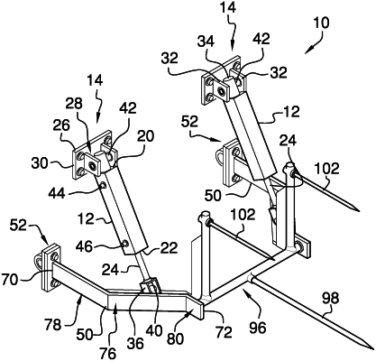
1. A hay bale fork assembly for facilitating a pair of hay bales to be transported simultaneously on an implement, said assembly comprising:
a pair of hydraulic cylinders, each of said hydraulic cylinders having a connection point being pivotally integrated onto said hydraulic cylinders wherein said connection point is configured to be connected to a rear end of a tractor;
a pair of mounting brackets, each of said mounting brackets having a connection point being integrated into said mounting brackets wherein said connection point on each of said mounting brackets is configured to be pivotally coupled to a respective first lateral side and a second lateral side of the tractor having each of said mounting brackets extending away from the rear end of the tractor, each of said mounting brackets being pivotally attached to a respective one of said hydraulic cylinders, each of said mounting brackets being urged between a lifted position and a lowered position when said hydraulic cylinders are respectively retracted and extended;
a lifting fork being coupled between each of said mounting brackets, said lifting fork being lifted when said mounting brackets is urged into said lifted position, said lifting fork being lowered when each of said mounting brackets is urged into said lowered position, said lifting fork having a first tine being disposed on said lifting fork wherein said first tine is configured to penetrate a first hay bale, said lifting fork having a pair of second tines each being disposed on said lifting fork wherein each of said second tines is configured to penetrate a second hay bale;
wherein said connection point on each of said mounting brackets includes a first plate having a primary surface and a secondary surface;
wherein said connection point on each of said mounting brackets includes a bearing being coupled to said primary surface of said first plate, said bearing having an opening extending through said bearing, said bearing being oriented such that said bearing has an axis of rotation being oriented parallel to said primary surface; and
wherein said assembly includes a pair of bolts, each of said bolts being extendable through a respective one of said bearings wherein each of said bolts is configured to engage a respective first lateral side and second lateral side of the tractor for pivotally attaching said bearings to the respective first lateral side and second lateral side of the tractor.
|