| CPC H05K 7/20145 (2013.01) [H05K 7/20172 (2013.01); H05K 7/20863 (2013.01); H05K 7/20909 (2013.01); B61C 17/00 (2013.01)] | 14 Claims |

|
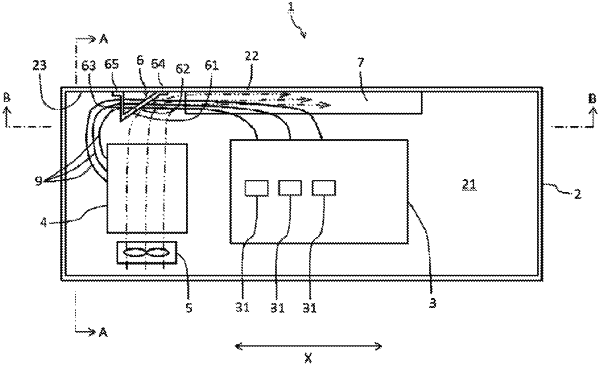
1. A propulsion control device comprising:
a housing;
a gate controller disposed at one end side of an interior space of the housing in a longitudinal axis direction, the gate controller being configured to control a power converter;
a fan disposed under the gate controller, the fan being configured to feed air to the gate controller;
an airflow guide member positioned relative to the gate controller at a side opposite to that of the fan, arranged at an interior face of a ceiling of the housing, and having an airflow guide face having a predetermined angle with respect to a vertical direction, the airflow guide member being configured to guide air passed through the gate controller to flow in a direction of airflow toward another end side of the interior space of the housing in the longitudinal axis direction; and
a plurality of wires led, from the gate controller toward the airflow guide member, to the side opposite to the direction of airflow and toward a ceiling side, the air passed through the gate controller being guided by the airflow guide member, wherein
the airflow guide member is a reinforcing beam including (i) a first member having the airflow guide face, and (ii) a second member extending toward the interior face of the ceiling and continuing from an end portion of the first member, the end portion being opposite to a side abutting against the ceiling, and
the first member and the second member of the airflow guide member each has a support hole to support the wires with the wires inserted therethrough.
|