| CPC H04L 1/0045 (2013.01) [H03K 19/01742 (2013.01); H03K 19/018521 (2013.01); H03K 19/21 (2013.01); H04L 1/0033 (2013.01); H04L 1/1678 (2013.01); H04L 7/0087 (2013.01); H04L 7/0331 (2013.01); H04L 27/3854 (2013.01); H04L 2027/0065 (2013.01)] | 20 Claims |

|
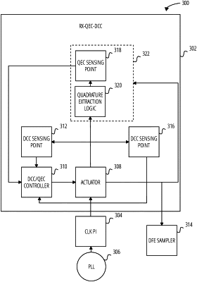
1. A clock signal correction circuit, comprising:
a first duty cycle correction loop of a plurality of duty cycle correction loops, the first duty cycle correction loop coupled to a plurality of clock signals and configured to:
receive a first set of clock signals from the plurality of clock signals; and
correct a duty cycle of the first set of clock signals; and
a first quadrature error correction loop of a plurality of quadrature error correction loops, the first quadrature error correction loop coupled to the plurality of clock signals and configured to:
receive a second set of clock signals from the plurality of clock signals having a first phase and a second phase, the first and second phases being distinct; and
correct a phase skew between the second set of clock signals; and
a digital correction controller coupled to the first duty cycle correction loop and the first quadrature error correction loop, the digital correction controller configured to update the duty cycle correction and the quadrature error correction based at least in part on the first or second set of clock signals.
|