| CPC H02P 21/22 (2016.02) [H02P 25/22 (2013.01)] | 8 Claims |

|
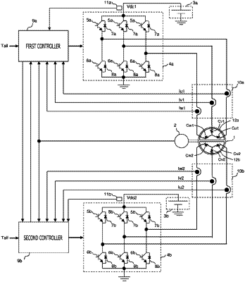
1. A motor controller that controls an AC rotary machine which has a first three-phase winding and a second three-phase winding, the motor controller comprising:
a first inverter that applies a first DC voltage of a first DC power source to the first three-phase winding;
a first current detector that detects a current which flows through the first three-phase winding;
a first controller that calculates a first d-axis current detection value and a first q-axis current detection value which are expressed a current detection value of the first three-phase winding detected by the first current detector in a coordinate system of a d-axis and a q-axis which rotates synchronizing with a rotational position of the AC rotary machine; calculates a first d-axis current command value and a first q-axis current command value; calculates a first d-axis voltage command value and a first q-axis voltage command value; and controls the first inverter based on the first d-axis voltage command value and the first q-axis voltage command value;
a second inverter that applies a second DC voltage of a second DC power source to the second three-phase winding;
a second current detector that detects a current which flows through the second three-phase winding; and
a second controller that calculates a second d-axis current detection value and a second q-axis current detection value which are expressed a current detection value of the second three-phase winding detected by the second current detector in the coordinate system of the d-axis and the q-axis; calculates a second d-axis current command value and a second q-axis current command value; calculates a second d-axis voltage command value and a second q-axis voltage command value; and controls the second inverter based on the second d-axis voltage command value and the second q-axis voltage command value,
wherein when determining that the first DC voltage is less than or equal to the second DC voltage, the first controller changes the first q-axis voltage command value so that the first q-axis current detection value approaches the first q-axis current command value, and
when determining that the first DC voltage is higher than the second DC voltage, the first controller changes the first q-axis voltage command value so that the first q-axis current detection value approach the second q-axis current detection value or the second q-axis current command value which are obtained from the second controller by communication,
wherein when determining that the second DC voltage is less than or equal to the first DC voltage, the second controller changes the second q-axis voltage command value so that the second q-axis current detection value approaches the second q-axis current command value, and
when determining that the second DC voltage is higher than the first DC voltage, the second controller changes the second q-axis voltage command value so that the second q-axis current detection value approaches the first q-axis current detection value or the first q-axis current command value which are obtained from the first controller by communication.
|