| CPC H02K 16/025 (2013.01) [B64C 27/10 (2013.01); B64D 27/24 (2013.01); H02K 5/1737 (2013.01); H02K 5/18 (2013.01); H02K 5/203 (2021.01); H02K 7/088 (2013.01); H02K 13/003 (2013.01); B64D 2221/00 (2013.01); H02K 9/19 (2013.01)] | 19 Claims |

|
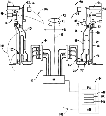
1. An electric machine (EM) for a drive system (DS) having a first DS rotor and a second DS rotor, the electric machine defining an axis and comprising:
a first EM rotor rotatable about the axis in a first circumferential direction and comprising a plurality of magnets, the first EM rotor configured for mechanical coupling to the first DS rotor; and
a second EM rotor rotatable about the axis in a second circumferential direction and comprising a plurality of windings, the second EM rotor configured for mechanical coupling to the second DS rotor and the plurality of magnets of the first EM rotor operably engaged with the plurality of windings of the second EM rotor; and
a first differential bearing positioned between the first EM rotor and the second EM rotor at a first position along the axis; and
a second differential bearing positioned between the first EM rotor and the second EM rotor at a second position along the axis, wherein the first position and the second position are on opposite sides of the plurality of magnets and the plurality of windings from one another.
|