| CPC H01M 4/13 (2013.01) [H01G 11/70 (2013.01); H01G 11/74 (2013.01); H01G 11/80 (2013.01); H01G 11/82 (2013.01); H01M 4/70 (2013.01); H01M 50/15 (2021.01); H01M 50/176 (2021.01); H01M 50/186 (2021.01); H01G 11/84 (2013.01); H01M 10/0525 (2013.01); H01M 50/533 (2021.01); H01M 50/534 (2021.01); H01M 50/536 (2021.01)] | 19 Claims |

|
1. An energy storage device, including:
a case;
a terminal portion;
a current collector; and
a connecting portion which penetrates the case and connects the terminal portion and the current collector,
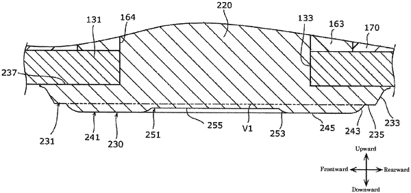
wherein the connecting portion includes a swaged portion which penetrates the terminal portion or the current collector and projects in a predetermined direction from the terminal portion or the current collector,
wherein the swaged portion includes:
a first convex portion which protrudes in the predetermined direction and includes a first tapered surface in an outer periphery of the first convex portion; and
a second convex portion which protrudes in the predetermined direction more than the first convex portion at an inner peripheral side of the first convex portion,
wherein an annular flat surface portion extends substantially parallel to the case and is formed between a circumference of the first convex portion and a circumference of the second convex portion, and
wherein the first tapered surface is formed such that a diameter of the outer periphery of the first convex portion is gradually decreased as the first convex portion extends away from the case.
|