| CPC H01H 50/60 (2013.01) [H01H 50/02 (2013.01); H01H 50/36 (2013.01); H01H 50/58 (2013.01); H01H 50/64 (2013.01)] | 9 Claims |

|
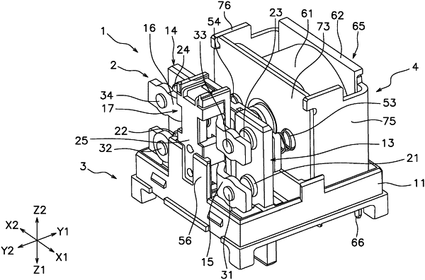
1. An electromagnetic relay comprising:
a first fixed terminal;
a first fixed contact connected to the first fixed terminal;
a second fixed terminal;
a second fixed contact connected to the second fixed terminal;
a first movable contact piece;
a first movable contact that faces the first fixed contact, the first movable contact being connected to the first movable contact piece;
a second movable contact that faces the second fixed contact, the second movable contact being connected to the first movable contact piece;
a moving member that holds the first movable contact piece, the moving member being made of a resin having electrical insulation, the moving member being configured to move in a moving direction including a first direction and a second direction, the first direction being a direction in which the first movable contact and the second movable contact come into contact with the first fixed contact and the second fixed contact respectively, the second direction being a direction in which the first movable contact and the second movable contact are separated from the first fixed contact and the second fixed contact respectively;
a housing that supports the moving member in a support direction perpendicular to the moving direction;
a coil; and
a movable iron core connected to the moving member, the movable iron core being configured to move by a magnetic force generated by the coil, wherein
the moving member includes
a first member connected to the movable iron core, and
a second member that is a separate body from the first member, the second member being connected to the first member by snap-fitting,
the first member includes a convex portion that projects toward the second member in the moving direction, and
the second member includes an inspection hole that faces the convex portion in the moving direction, the inspection hole extending in the moving direction.
|