| CPC H01G 4/30 (2013.01) [H01G 4/008 (2013.01); H01G 4/012 (2013.01); H01G 4/1218 (2013.01)] | 14 Claims |

|
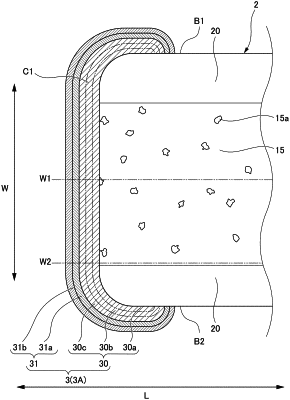
1. A multilayer ceramic capacitor comprising:
a multilayer body including dielectric layers and internal electrode layers alternately laminated therein; and
external electrodes respectively provided on both end surfaces of the multilayer body in a length direction intersecting a lamination direction, and each connected to the internal electrode layers; wherein
a positional deviation in the lamination direction between end portions in a width direction intersecting the lamination direction and the length direction, of two of the internal electrode layers adjacent to each other in the lamination direction, is about 5 μm or less; and
when a number of all of the internal electrode layers extending to one of the external electrodes is defined as N0, a number of the internal electrode layers connected to the one of the external electrodes in a cross-section extending in the length direction and the lamination direction and passing through a middle portion thereof in the width direction is defined as N1, and a number of the internal electrode layers connected to the one of the external electrodes in a cross-section extending in the length direction and the lamination direction and passing through an end portion thereof in the width direction is defined as N2:
a connection ratio N1/N0 at the middle portion thereof, and a connection ratio N2/N0 at the end portion thereof are about 90% or more, respectively; and
a difference between the connection ratio N1/N0 and the connection ratio N2/N0 is about 10% or less.
|