| CPC G11C 16/08 (2013.01) [G11C 16/0483 (2013.01); G11C 16/32 (2013.01); G11C 16/26 (2013.01)] | 14 Claims |

|
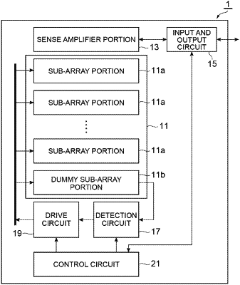
1. A drive circuit for driving a plurality of linearly arranged cells through a linear wiring portion connected to the plurality of cells, comprising:
a voltage application circuit configured to generate a drive voltage in which a pre-pulse having a predetermined amplitude value is set at a timing corresponding to rising or falling of a voltage signal changing stepwise by a predetermined voltage value, and apply the drive voltage to the wiring portion; and
a controller configured to detect a voltage value at a predetermined position of the wiring portion and set a time width of the pre-pulse according to the detected voltage value,
wherein the controller sets the time width by comparing a target value set in advance with the voltage value and turning on/off the pre-pulse according to a result of the comparison, and
the target value is set in advance based on the predetermined voltage value and the predetermined amplitude value.
|