| CPC G06F 3/0418 (2013.01) [G09G 3/035 (2020.08); G09G 3/3233 (2013.01); G06F 3/0446 (2019.05); G09G 2300/0842 (2013.01); G09G 2310/0286 (2013.01); G09G 2320/0233 (2013.01); G09G 2320/0626 (2013.01); G09G 2354/00 (2013.01)] | 15 Claims |
|
1. A display device including: a display panel having a display element configured to emit light at luminance determined based on an amount of current supplied to the display element; and a touch panel provided on a front side of the display panel, the display device comprising:
a sensor value obtaining circuit configured to obtain a sensor value that changes depending on a degree of approach of a detection object to the touch panel;
a touch position identifying circuit configured to identify a touch position, the touch position being a position in which the detection object touches the touch panel; and
a correction value calculation circuit configured to determine a correction value for correcting the sensor value so that influence by temperature is removed when the touch position identifying circuit identifies the touch position, wherein
the sensor value obtaining circuit obtains in advance a first reference value and a second reference value, the first reference value being a sensor value obtained when the display element does not emit light in normal temperature state, and the second reference value being a sensor value obtained when the display element emits light in normal temperature state,
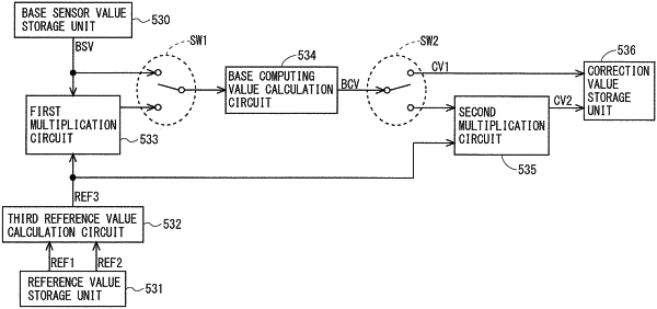
the correction value calculation circuit includes:
a correction value storage unit configured to store the correction value for each node, the node being a unit for obtaining the sensor value; and
a base computing value calculation circuit configured to determine, for each node, a base computing value representing a ratio of a predetermined reference value to an input value,
an upper limit value and a lower limit value are set for the base computing value determined by the base computing value calculation circuit,
the correction value calculation circuit:
stores, for a node in which a difference between a base sensor value and the first reference value is less than a predetermined threshold value, a base computing value obtained by providing the base sensor value as the input value to the base computing value calculation circuit as the correction value in the correction value storage unit, the base sensor value being a sensor value obtained at certain time intervals by the sensor value obtaining circuit; and
stores, for a node in which a difference between a base sensor value and the first reference value is greater than the threshold value, a product of a base computing value and a third reference value as the correction value in the correction value storage unit, the third reference value representing a ratio of the first reference value to the second reference value, and the base computing value being obtained by providing a product of the third reference value and the base sensor value as the input value to the base computing value calculation circuit, and
the touch position identifying circuit identifies the touch position based on values obtained by correcting, by using correction values stored in the correction value storage unit, sensor values obtained most recently by the sensor value obtaining circuit.
|