| CPC G04B 13/028 (2013.01) [G04B 13/026 (2013.01); G04B 27/001 (2013.01); G04B 27/004 (2013.01)] | 14 Claims |

|
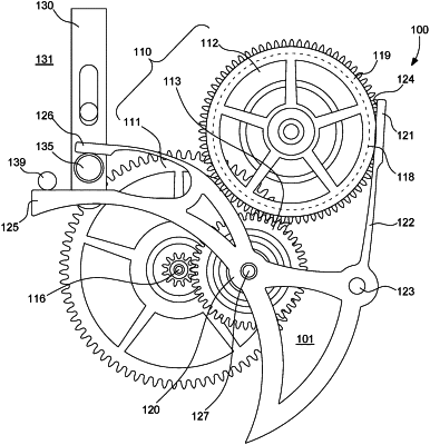
1. A timepiece mechanism (100) for disengaging a gear train, said timepiece mechanism (100) comprising at least:
at least one gear set (110) comprising a first wheel (111), a second wheel (112) and an intermediate wheel (113) arranged between said first wheel (111) and said second wheel (112); said intermediate wheel (113) being configured to be driven by or for driving said first wheel (111) and/or said second wheel (112);
at one disengagement member (120) configured to move said intermediate wheel (113) in a movement plane between an engaged position (101) in which said first wheel (111), said intermediate wheel (113) and said second wheel (112) are kinematically connected and a disengaged position (102) in which said intermediate wheel (113) is unmeshed from said first wheel (111) and/or from said second wheel (112);
at least one holding member (121) configured to hold said first wheel (111) and/or said second wheel (112); and
at least one control member (130) configured to move said at least one disengagement member (120) between said engaged position (101) and said disengaged position (102) and to move said at least one holding member (121) into contact and to hold said first wheel (111) and/or said second wheel (112) when said at least one disengagement member (120) is in the disengaged position (102),
wherein said at least one disengagement member (120) comprises at least one first flexible arm (122) configured to connect said at least one holding member (121) to said at least one disengagement member (120),
wherein said first wheel (111) and/or said second wheel (112) comprises a friction surface (118),
wherein said at least one holding member (121) has a holding surface (124) configured to cooperate with said friction surface (118) of said first wheel (111) and/or said second wheel (112),
wherein the holding of said first wheel and/or of said second wheel by said holding surface is performed by friction or lubricated friction allowing the user a manual correction in the disengaged position (102), and
wherein said at least one control member is slidably movable in translation between a first position and a second position to move said at least one disengagement member (120) between said engaged position (101) and said disengaged position (102) and to move said at least one holding member (121) into contact and to hold said first wheel (111) and/or said second wheel (112) when said at least one disengagement member (120) is in the disengaged position (102).
|