| CPC F24D 19/1009 (2013.01) [F24D 19/1015 (2013.01); G08B 21/20 (2013.01); F24D 2220/046 (2013.01)] | 20 Claims |

|
1. A boiler overflow preventer system, comprising:
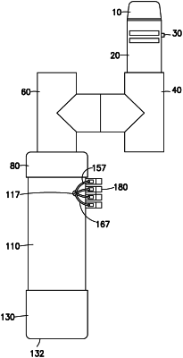
a. a housing having a top end connected to a first in-line arm of a first fluid Tee joint, also having a second in-line arm and a transverse arm, a bottom end removably capped with a cap, and an internal cavity between the top end and the bottom end in fluid communication with the second in-line arm, said second in-line arm being adapted to be to removably connected to a pressure relief valve of a boiler, with an aperture in the housing allowing access to the internal cavity for electrical wiring;
b. a cooperating core for insertion into the internal cavity, said cooperating core having a first open end and a second open end and at least one aperture therebetween for the electrical wiring;
c. a plurality of float switches or air pressure switches mounted in the cooperating core between the first open end and the second open end, said plurality of float switches or air pressure switches being electrically connected to at least one limit switch of a boiler by the electrical wiring passing through the aperture in the housing and through the at least one aperture in the cooperating core when the cooperating core is inserted into the internal cavity and the bottom end of the housing is capped with the cap;
d. a second Tee joint having a transverse arm connected to the transverse arm of the first fluid Tee joint; and
e. an alarm module connected to an upward in-line arm of the second Tee joint and in electrical communication with the plurality of float switches or air pressure switches, wherein the water from the pressure relief valve accumulates in the internal cavity of the housing through the second in-line arm and fills the cooperating core therein, activating the plurality of float switches or air pressure switches mounted in the cooperating core when the water reaches the plurality of float switches or when the air pressure builds up in the internal cavity and opening or closing an electrical circuit connected to the at least one limit switch and, wherein excess water is discharged from the housing through a downward in-line arm of the second Tee joint opposite to the upward in-line arm.
|