| CPC F21S 41/295 (2018.01) [F21S 41/265 (2018.01); F21S 43/145 (2018.01); F21Y 2105/10 (2016.08)] | 19 Claims |

|
1. A lighting device of a motor vehicle headlamp comprising:
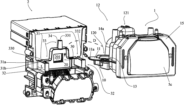
a projection optics system (1); and
a light source unit (2), wherein the light source unit comprises a surface (20), wherein:
the light source unit (2) can generate a lighting pattern on the surface (20), wherein the lighting pattern which can be generated on the surface (20) can be projected in front of the lighting device in the form of a light distribution by means of the projection optics system (1),
the light source unit (2) comprises a support structure (3),
the support structure (3) has an opening (30), wherein the opening (30) is arranged and designed to match the surface (20) and the lighting pattern can be generated at least on one side (201) of the surface (20) facing the projection optics system (1),
the projection optics system (1) has guiding elements (10) and the support structure (3) has elongated guides (31) corresponding to the guiding elements (10), wherein the guiding elements (10) are arranged in such a way that they can be guided in the elongated guides (31) along a longitudinal direction (X) of the elongated guides (31),
the projection optics system (1) rests on the support structure (3), is movable along the longitudinal direction (X) and can be fastened to the support structure (3), and
the projection optics system (1) is movable within a range of movement (B) defined by the length (L) of the elongated guides (31) and the projection optics system (1) has a fastening region (12) and the support structure (3) has a counter-region (33) corresponding to the fastening region (12), wherein the range of movement (B), fastening region (12) and the counter-region (33) correspond to each other in such a way that the projection optics system (1) can be fastened to the support structure (3) in any position within the range of movement (B) in such a way that the fastening region (12) of the projection optics system (1) is at least partially fastened to the counter-region (33) of the support structure (3).
|