| CPC F04D 15/0066 (2013.01) [F04D 13/14 (2013.01); F04D 29/406 (2013.01); F04D 29/4293 (2013.01); F04D 13/06 (2013.01); F04D 15/029 (2013.01); F05D 2270/02 (2013.01)] | 28 Claims |

|
1. A pump unit, comprising:
a casing including a suction flange and a discharge flange;
a first pump impeller within the casing;
a second pump impeller within the casing and which provides a parallel hydraulic path to the first pump impeller;
wherein the first pump impeller is configured to concurrently rotate in an opposite rotational direction to the second pump impeller;
a first back pressure activated flow prevention flap to permit flow from the first pump impeller to the discharge flange and which is rotatable;
a second back pressure activated flow prevention flap to permit flow from the second pump impeller to the discharge flange and which is independently rotatable from the first back pressure activated flow prevention flap, wherein the first back pressure activated flow prevention flap abuts the second back pressure activated flow prevention flap when one or both are rotated towards each other;
a first suction bay hydraulically fed from the suction flange;
a second suction bay hydraulically fed from the suction flange;
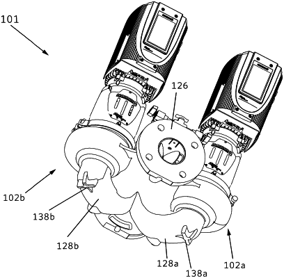
wherein the casing has a flat bottom surface of exactly two flat regions of contact comprising a first exterior flange and a second exterior flange;
wherein the first exterior flange has a first flattened surface and is integrally formed to and positioned directly below the first suction bay, wherein the first exterior flange extends lower than the suction flange and the discharge flange when the pump unit is vertically oriented;
wherein the second exterior flange has a second flattened surface and is integrally formed to and positioned directly below the second suction bay, wherein the second exterior flange extends lower than the suction flange and the discharge flange when the pump unit is vertically oriented;
wherein the first exterior flange and the second exterior flange are horizontally aligned when the pump unit is vertically oriented, so that the first exterior flange and the second exterior flange collectively provide the flat bottom surface;
wherein the first exterior flange and the second exterior flange each have a flat cross shape that collectively define the flat bottom surface; and
wherein the suction flange and the discharge flange are floating and above the first exterior flange and the second exterior flange when the pump unit is vertically oriented.
|