US 11,732,653 B2
System and method for purging a fuel manifold of a gas turbine engine through a flow divider valve
James Robert Jarvo, Saint-Bruno-de-Montarville (CA); Cédric Saintignan, Montreal (CA); Joseph Daniel Maxim Cirtwill, Gravenhurst (CA); Kian McCaldon, Orangeville (CA); Marc-Andre Tremblay, Montreal (CA); and David Waddleton, Candiac (CA)
Assigned to PRATT & WHITNEY CANADA CORP., Longueuil (CA)
Filed by PRATT & WHITNEY CANADA CORP., Longueuil (CA)
Filed on Nov. 17, 2022, as Appl. No. 17/989,247.
Application 17/989,247 is a division of application No. 16/871,130, filed on May 11, 2020.
Claims priority of provisional application 62/848,223, filed on May 15, 2019.
Claims priority of provisional application 62/848,187, filed on May 15, 2019.
Claims priority of provisional application 62/848,196, filed on May 15, 2019.
Claims priority of provisional application 62/848,231, filed on May 15, 2019.
Claims priority of provisional application 62/849,428, filed on May 17, 2019.
Claims priority of provisional application 62/850,809, filed on May 21, 2019.
Prior Publication US 2023/0083847 A1, Mar. 16, 2023
This patent is subject to a terminal disclaimer.
Int. Cl. F02C 7/30 (2006.01); F02C 7/228 (2006.01); F02C 6/00 (2006.01); F02C 6/16 (2006.01); F02C 7/22 (2006.01); F02C 7/236 (2006.01); F02C 9/32 (2006.01); F02C 9/42 (2006.01); F02C 7/232 (2006.01)
CPC F02C 7/30 (2013.01) [F02C 6/00 (2013.01); F02C 6/16 (2013.01); F02C 7/222 (2013.01); F02C 7/228 (2013.01); F02C 7/232 (2013.01); F02C 7/236 (2013.01); F02C 9/32 (2013.01); F02C 9/42 (2013.01)] 8 Claims
OG exemplary drawing
 
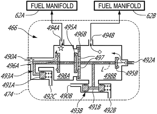
1. A fuel system of a gas turbine engine, the fuel system comprising:
a pressurized gas source;
a first fuel manifold fluidly connectable to a combustor of the gas turbine engine;
a second fuel manifold fluidly connectable to the combustor; and
a flow divider valve actuatable between a first configuration and a second configuration, wherein:
in the first configuration, the flow divider valve is configured to supply fuel to the first and second fuel manifolds; and
in the second configuration, the flow divider valve is configured to:
supply fuel to the first fuel manifold,
stop supplying fuel to the second fuel manifold, and
permit pressurized gas to be supplied from the pressurized gas source to the second fuel manifold to flush fuel in the second fuel manifold into the combustor.