| CPC F01D 25/32 (2013.01) [F01D 5/18 (2013.01); F01D 9/041 (2013.01); F05D 2220/31 (2013.01); F05D 2260/602 (2013.01)] | 7 Claims |

|
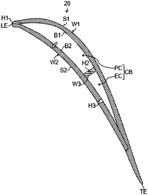
1. A steam turbine hollow stationary blade, that has a cavity therein, comprising:
a partition wall dividing the cavity into a pressure chamber on a leading edge side and an exhaust chamber on a trailing edge side;
at least one steam inlet hole connecting the pressure chamber and an outside of the stationary blade to each other, wherein the at least one steam inlet hole is positioned on a leading edge of the stationary blade; and
at least one pressure conditioning hole connecting the pressure chamber and the exhaust chamber, wherein
total opening area of the at least one pressure conditioning hole is smaller than total opening area of the at least one steam inlet hole such that a pressure in the pressure chamber is increased to the extent that the pressure chamber is higher in temperature than a turbulent boundary layer formed on the stationary blade along the pressure side surface thereof;
the at least one steam inlet hole is a hole that connects the pressure chamber to a working medium flow channel in which the steam flows as a working medium.
|