|
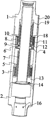
1. A fully electrically controlled intelligent subsurface safety valve, comprising an external component, a magnetic excitation switch, an upper electromagnetic suction module, a lower electromagnetic suction module, and a rebound flap valve mechanism, wherein the external component is composed of an upper joint, a lower joint, a valve shell, a flow sensor, a power communication composite cable connector, a sealing cover, a PLC controller, and a temperature and pressure sensor; the magnetic switch is composed of a magnetic piston ring, a spring, a thrust bearing, a central flow tube, a guide sleeve and a locking sleeve; the upper electromagnetic suction module and the lower electromagnetic suction module are both composed of a magnetic isolation collar, an annular wire rack, a annular iron core, a circular coil, and an outer sleeve; and the rebound flap valve mechanism is composed of a valve seat, a plate valve, and a displacement sensor; wherein the upper joint is connected to the valve shell through threads, the valve shell is provided with a first valve shell through hole, a second valve shell through hole, a first step, and a second step; the central flow pipe is arranged between the upper joint and the plate valve, the locking sleeve is connected to the upper joint through threads, the guide sleeve is arranged between the locking sleeve and the central flow pipe, the upper electromagnetic suction module is arranged between the upper joint and the first step, the magnetic piston ring is connected with the central flow pipe through threads, the magnetic piston ring is matched with the valve shell in a clearance fit, the spring is arranged between the central flow pipe and the valve seat, the lower electromagnetic suction module is arranged between the second step and the valve seat, the valve seat is connected with the valve shell through threads, the lower joint is connected with the valve shell through threads, the displacement sensor is provided on the plate valve, the flow sensor is provided on an inner wall of the lower joint, and the temperature and pressure sensor is arranged inside the lower joint.
|
