| CPC E05F 3/14 (2013.01) [A47K 13/12 (2013.01); F16F 9/16 (2013.01); E05Y 2201/212 (2013.01); E05Y 2201/224 (2013.01); E05Y 2201/638 (2013.01)] | 9 Claims |

|
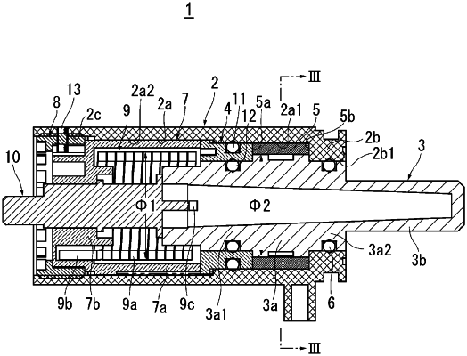
1. A damper device comprising:
a case,
a shaft that is relatively rotatable with respect to the case,
fluid filled in a damper chamber formed between the case and the shaft,
a bearing member that forms a partition wall that closes one end of the damper chamber in an axial direction and is separate from the shaft, and
a coil spring having one end connected to a side of the case and the other end connected to the shaft or the bearing member to apply torque to the shaft with respect to the case,
wherein the bearing member is arranged between a winding portion of the coil spring and the damper chamber, and the winding portion of the coil spring and the damper chamber are separated from each other in the axial direction,
wherein a sliding sealing member is arranged between the bearing member and the shaft that is rotatable with respect to the bearing member, and a fixed sealing member is arranged between the case and the bearing member that is non-rotatable with respect to the case.
|