| CPC B25C 1/008 (2013.01) [B25C 1/047 (2013.01); B25C 1/06 (2013.01)] | 15 Claims |

|
1. A driver machine configured for use in a fastener driving tool, said driver machine comprising:
(a) a hollow cylinder having a movable piston therewithin;
(b) a guide body that is sized and shaped to receive a fastener that is to be driven;
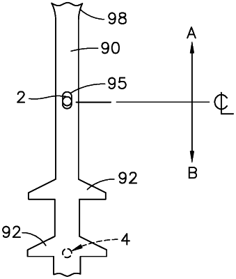
(c) an elongated driver that is in mechanical communication with said piston during a driving stroke, said driver being sized and shaped to push said fastener from an exit portion of said guide body, said driver extending from a first end to a second end and having an elongated face therebetween, said first end being proximal to said piston, said second end being distal from said piston and making contact with said fastener during said driving stroke, said driver having an opening at a predetermined location in said elongated face that extends completely through said driver;
(d) a lifter that, under first predetermined conditions, moves said driver toward a ready position during a return stroke;
(e) an electrical energy source;
(f) a first position sensor which detects said driver opening if said driver is correctly located at a driven position after said driving stroke;
(g) a piston stop located between the hollow cylinder and the guide body; and
(h) a system controller comprising: (i) a processing circuit, (ii) a memory circuit including instructions executable by said processing circuit, (iii) an input/output interface (I/O) circuit, said I/O circuit being in communication with said first position sensor so that a first signal produced by said first position sensor is received as a first input signal at said processing circuit;
wherein: said system controller is configured:
(i) under second predetermined conditions, to allow said driver to undergo said driving stroke, thereby moving said driver toward said driven position;
(ii) to determine a start time TX at a beginning of said driving stroke;
(iii) after said time TX occurs, to wait for a time interval TB, then to determine if said first input signal is at a first logic state or a second logic state, such that: (A) if said first position sensor does not detect said driver opening, then said first input signal will be at said first logic state, and (B) if said first position sensor does detect said driver opening, then said first input signal will be at said second logic state;
(iv) if said first input signal is at said first logic state after said time interval TB, then said driver machine is operating abnormally; and
(v) if said first input signal is at said second logic state after said time interval TB, then said driver machine is operating normally;
wherein: said driver opening is sized and shaped so as to prevent the first input signal to be at said second logic state if, after the driving stroke, the driver is located at a position that is too far toward the guide body, due to excessive wear of the piston stop.
|