| CPC B21D 53/84 (2013.01) [B23B 3/065 (2013.01); B23C 3/30 (2013.01); B23Q 1/52 (2013.01); B23B 1/00 (2013.01); B23C 2215/245 (2013.01); B23P 2700/04 (2013.01)] | 17 Claims |

|
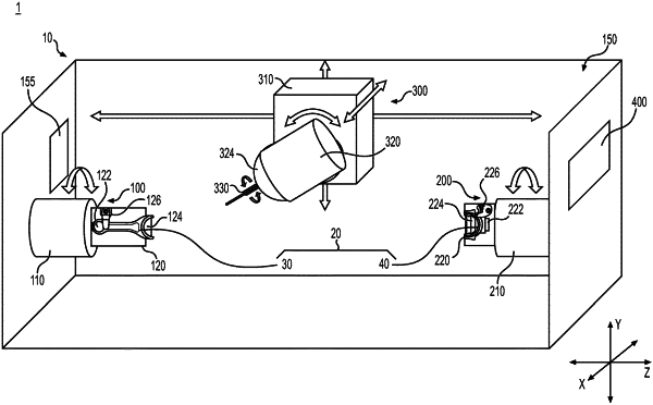
1. A method of manufacturing an engine connecting rod assembly using a machine, the engine connecting rod assembly including a rod and a cap, the method comprising:
mounting the rod on a first mount configured to rotate, the rod having a first connecting end;
mounting the cap on a second mount configured to rotate, the cap having a second connecting end configured to be coupled to the first connecting end;
positioning a spindle head such that a tool of the spindle head contacts the first connecting end;
machining the first connecting end by spinning the first mount;
machining the first connecting end by moving the spindle head;
positioning the spindle head such that the tool of the spindle head contacts the second connecting end;
machining the second connecting end by spinning the second mount; and
machining the second connecting end by moving the spindle head, wherein the spindle head is moveable in a first direction, moveable in a second direction perpendicular to the first direction, moveable in a third direction perpendicular to the first and second directions, and rotatable about an axis, and wherein the first direction extends between the first and second mounts.
|