| CPC G02B 26/085 (2013.01) [B81B 3/00 (2013.01); G02B 7/182 (2013.01); G02B 26/0841 (2013.01); G02B 26/10 (2013.01)] | 17 Claims |
|
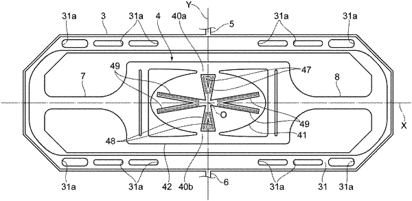
1. A mirror device comprising:
a support portion;
a movable portion; and
a pair of first torsion bars disposed on both sides of the movable portion on a first axis and connecting the movable portion to the support portion so that the movable portion is swingable around the first axis as a center line,
wherein one surface of the movable portion is provided with a mirror surface, and the other surface of the movable portion is provided with a beam structure,
the movable portion includes a silicon portion and a metal film, and the mirror surface is formed by the metal film,
the beam structure includes a first V-shaped beam structure, a second V-shaped beam structure, a third V-shaped beam structure, and a fourth V-shaped beam structure,
each of the first to fourth V-shaped beam structures includes a base end portion and a pair of extending portions extending from the base end portion,
the base end portion of each of the first to fourth V-shaped beam structures is located on a central region of the movable portion,
when viewed from a third direction perpendicular to both a first direction parallel to the first axis and a second direction parallel to a second axis perpendicular to the first axis,
the pair of extending portions of the first V-shaped beam structure extend from the central region toward one side in the first direction on both sides of the first axis,
the pair of extending portions of the second V-shaped beam structure extend from the central region toward the other side in the first direction on both sides of the first axis,
the pair of extending portions of the third V-shaped beam structure extend from the central region toward one side in the second direction on both sides of the second axis,
the pair of extending portions of the fourth V-shaped beam structure extend from the central region toward the other side in the second direction on both sides of the second axis, and
the pair of extending portions of each of the first to fourth V-shaped beam structures are spaced apart from each other.
|