| CPC F16F 9/512 (2013.01) [F16F 9/062 (2013.01); F16F 9/348 (2013.01)] | 7 Claims |
|
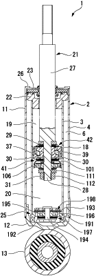
1. A shock absorber comprising:
a cylinder which is filled with a working fluid;
a piston which is slidably provided in the cylinder and divides an inside of the cylinder into one side chamber and another side chamber;
a piston rod which is connected to the piston and extends outside the cylinder;
a first passage and a second passage through which the working fluid flows from a chamber on an upstream side to a chamber on a downstream side in the cylinder by a movement of the piston;
a first damping force generating mechanism which is provided in the first passage provided in the piston and generates a damping force; and
a second damping force generating mechanism which is provided in an annular valve seat member disposed in the other side chamber, is provided in the second passage which is parallel to the first passage, and generates a damping force,
wherein the second damping force generating mechanism includes
a first sub valve provided on one side of valve seat member including a passage hole which forms a part of the second passage, and a second sub valve provided on another side of the valve seat member, and
a bottomed tubular cap member provided between the piston and the valve seat member in the second passage,
the valve seat member is provided in the cap member, the first sub valve is provided in the other side chamber, and the second sub valve is provided in a cap chamber between a bottom portion of the cap member and the valve seat member,
in the second passage, an orifice is disposed on an upstream side or a downstream side from the first sub valve in flow by which the first sub valve is opened,
in a region in which a piston speed is low, a valve of the second damping force generating mechanism is opened in a state in which a valve of the first damping force generating mechanism is closed, and
in a speed region in which the piston speed is higher than that in the region in which the piston speed is low, the valve of the first damping force generating mechanism and the valve of the second damping force generating mechanism are both opened.
|