|
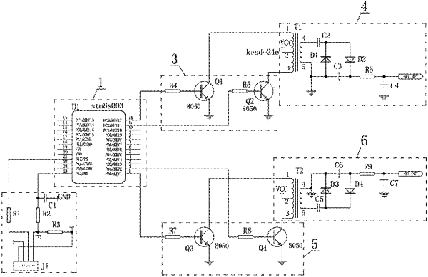
1. A laminar electrostatic eliminator circuit, comprising a main control module, a control instruction sending unit, a first driving circuit, a first boost circuit, a second driving circuit, and a second boost circuit, wherein a signal input terminal of the main control module is connected to an instruction sending terminal of the control instruction sending unit, a first control terminal and a second control terminal of the main control module are connected to an input terminal of the first driving circuit and an input terminal of the second driving circuit respectively, an output terminal of the first driving circuit is connected to an input terminal of the first boost circuit, and an output terminal of the first boost circuit is connected to a positive high voltage terminal output; and an output terminal of the second driving circuit is connected to an input terminal of the second boost circuit, and an output terminal of the second boost circuit is connected to a negative high voltage terminal output, wherein the control instruction sending unit comprises a pin header J1, a resistor R1, a resistor R2, and a resistor R3, a pin 1 of the pin header J1 is connected to a negative-high-voltage generating control signal terminal input, and is connected to an input terminal of the resistor R3, an output terminal of the resistor R3 is connected to an input terminal of the resistor R2, and is connected to a pin 4 of the pin header J1, an output terminal of the resistor R2 is connected to a pin 24 of the chip U1 as a main control chip of the main control module, and is connected to an input terminal of a capacitor C1, an output terminal of the capacitor C1 is grounded, and a pin 2 of the pin header J1 is connected to a positive-high-voltage generating control signal terminal input.
|
