| CPC H02K 1/148 (2013.01) [H02K 1/16 (2013.01); H02K 3/28 (2013.01); H02K 11/33 (2016.01)] | 10 Claims |

|
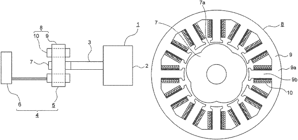
1. A redundancy resolver device, comprising:
a resolver main body including a stator, and a rotor rotatable with respect to the stator; and
a controller including a plurality of excitation circuits,
the stator including a stator core, and winding groups of a plurality of systems provided in the stator core,
the stator core including a core back portion, and a plurality of teeth which protrude from the core back portion,
the winding groups of different systems being arranged at different positions in a circumferential direction of the stator core,
the winding groups of each of the plurality of systems including:
an excitation winding group consisting of a plurality of excitation windings, and being connected to a corresponding one of the plurality of excitation circuits;
a first output winding group consisting of a plurality of first output windings; and
a second output winding group consisting of a plurality of second output windings,
each of the plurality of teeth having a corresponding one of the plurality of excitation windings wound therearound, and
where two of the plurality of excitation windings belonging to different systems and being arranged side by side in the circumferential direction of the stator core are defined as a first end excitation winding and a second end excitation winding, respectively, the first end excitation winding and the second end excitation winding are supplied with excitation signals to generate magnetic fluxes in the same radial directions of the stator core.
|