| CPC H02H 9/001 (2013.01) [H02H 9/025 (2013.01); H02M 1/36 (2013.01)] | 20 Claims |

|
1. A device comprising:
a processor;
memory for storing instruction code that is executable by the processor; and
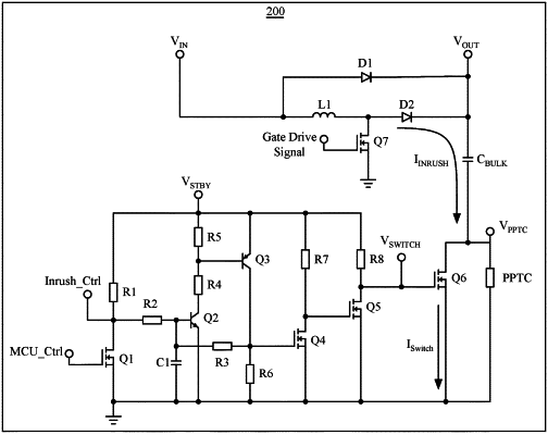
power supply circuitry in communication with the processor, wherein the power supply circuitry comprises:
voltage regulator circuitry that comprises an input electrically coupled to a voltage source and an output configured to provide a regulated voltage output;
a capacitor configured to store energy derived from the voltage source, wherein the capacitor comprises (1) a first terminal electrically coupled to the output of the voltage regulator circuitry and (2) a second terminal;
a current limiter having a third terminal and a fourth terminal, the third terminal being connected to the second terminal of the capacitor to form a first node, the current limiter being configured to limit inrush current through the capacitor during a start-up phase of the power supply circuitry; and
a switch circuit comprising a transistor having (1) a drain terminal that also forms the first node with the second terminal of the capacitor and the third terminal of the current limiter and (2) a source terminal that forms a second node with the fourth terminal of the current limiter, wherein capacitor current flows through the switch circuit when the switch circuit is in an ON state, substantially bypassing the current limiter, wherein the switch circuit is transitioned to the ON state when a particular control signal is applied to the switch circuit, wherein the switch circuit is configured to remain in the ON state when the particular control signal is no longer applied to the switch circuit.
|