| CPC H01M 50/502 (2021.01) [H01M 50/204 (2021.01); H01M 50/505 (2021.01); H01M 50/509 (2021.01); H01M 50/528 (2021.01)] | 6 Claims |

|
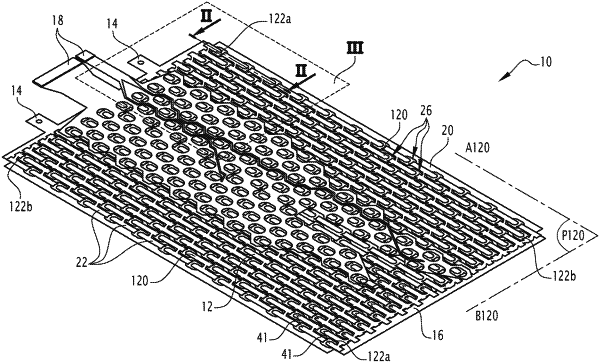
1. A laminated busbar for interconnecting electrical storage devices, comprising:
an insulating layer;
at least one conductive band arranged on the insulating layer, the at least one conductive band comprising a succession of repeating conductor patterns, each conductor pattern defining a cluster having a first terminal and a second terminal for connection to an energy storage device; and
a first terminator coupled to the first terminal and a second terminator coupled to the second terminal, the first and second terminators configured to connect to terminals of the energy storage device,
wherein each conductive band is made from pre-stamped metal coil,
wherein the insulating layer comprises a top layer and a bottom layer, wherein each conductive band is laminated between the top layer and the bottom layer, the conductive band and the top and bottom layers forming a laminated band,
wherein each one of the top and bottom layers comprises openings, configured to allow access to each terminator from both sides of the laminated band,
wherein two terminators configured to connect to the same energy storage device define a connection gap,
wherein at least one of the top or bottom layers comprises first openings, which are each configured to allow access to a respective connection gap,
wherein the at least one conductive band is arranged along a longitudinal axis and comprises two opposite extremity portions,
wherein each conductor is arranged along a transverse axis, two consecutive conductors being periodically spaced from each other along the longitudinal axis,
wherein each conductor has the same number of clusters, the clusters of one conductor being arranged along the transverse axis, two consecutive clusters of a same conductor pattern being periodically spaced from each other along the transverse axis,
wherein all first terminals of the laminated busbar are connectable to a first electric pole of an energy storage device, while all second terminals are connectable to a second electric pole of an energy storage device,
wherein each extremity portion is configured, when connected to a respective energy storage device, to have a polarity opposite to the other extremity portion and is configured to connect to a termination conductor or to a junction bar,
wherein the busbar comprises a laminated busbar and two termination conductors,
wherein the laminated busbar comprises one laminated band, wherein the two extremity portions of said one laminated band are each connected to a respective termination conductor,
wherein the laminated busbar comprises a pair of two laminated bands, two termination conductors and a junction bar,
wherein the longitudinal axes of each conductive band of said pair are parallel to each other,
wherein at least one conductor and at least one extremity portion of one laminated band of said pair are aligned, along the transverse axis, respectively with a conductor and with an extremity portion of the other conductive band of said pair,
wherein the two extremity portions that are aligned with each other along the transverse axis have opposite polarities,
wherein the two extremity portions that are aligned along the transverse axis are coupled together by a junction bar,
wherein the other two extremity portions are each configured to be coupled to a respective termination conductor.
|