| CPC H01M 50/15 (2021.01) [H01M 50/103 (2021.01); H01M 50/342 (2021.01); H01M 50/383 (2021.01); H01M 50/394 (2021.01); H01M 2220/20 (2013.01)] | 18 Claims |

|
1. An end cover assembly (100), applied in an energy storage apparatus (200) comprising an electrode assembly (210), the end cover assembly (100) comprising:
a top cover (10) having a first surface (11) and a second surface (13) facing away from the first surface (11), the top cover (10) having an explosion-proof hole (15) through the first surface (11) and the second surface (13), the top cover (10) having a length direction and a width direction, and a length of the top cover (10) in the length direction being greater than a length of the top cover (10) in the width direction;
an explosion-proof sheet (20) configured to seal the explosion-proof hole (15) and connected to the top cover (10); and
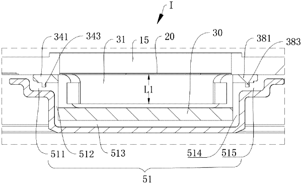
a shielding member (30) located at a side of the explosion-proof sheet (20) close to the second surface (13), the shielding member (30) being connected to the top cover (10), the top cover (10), the explosion-proof sheet (20), and the shielding member (30) forming a chamber (31), wherein the shielding member (30) has a plurality of first air vents (33) arranged at intervals along a peripheral side wall of the shielding member (30), the plurality of first air vents (33) being in communication with the chamber (31) and in communication with a space where the electrode assembly (210) of the energy storage apparatus (200) is located, the plurality of first air vents (33) comprising a first group of first air vents (33a) and a second group of first air vents (33b), a first air vent (33) in the first group of first air vents (33a) extending in the length direction of the top cover (10), and a first air vent (33) in the second group of first air vents (33b) extending in the width direction of the top cover (10), and wherein the shielding member (30) comprises a first connection portion (34), a first bent portion (35), a shielding portion (36), a second bent portion (37), and a second connection portion (38) that are sequentially bent and connected to each other, the first connection portion (34) and the shielding portion (36) being respectively located at two opposite sides of the first bent portion (35), the first bent portion (35) and the second bent portion (37) being located at one side of the shielding portion (36), the shielding portion (36) and the second connection portion (38) being respectively located at two opposite sides of the second bent portion (37), the shielding portion (36) and the explosion-proof sheet (20) being spaced apart from each other, the first connection portion (34) and the second connection portion (38) being spaced apart from each other in the length direction of the top cover (10), each of the first connection portion (34) and the second connection portion (38) being connected to the second surface (13) of the top cover (10), the first connection portion (34) comprising a first body portion (341) and a first protrusion portion (343) connected to the first body portion (341), the first body portion (341) being connected to the second surface (13) of the top cover (10), the first protrusion portion (343) protruding from a side of the first body portion (341) facing away from the top cover (10), the second connection portion (38) comprising a second body portion (381) and a second protrusion portion (383) connected to the second body portion (381), the second body portion (381) being connected to the second surface (13) of the top cover (10), and the second protrusion portion (383) protruding from a side of the second body portion (381) facing away from the top cover (10), wherein:
a ratio of a length W1 of the first air vent (33) in the first group of first air vents (33a) in the length direction of the top cover (10) to a maximum length D1 of the explosion-proof sheet (20) in the length direction of the top cover ranges from 0.8 to 1.2; and
a ratio of a length W2 of the first air vent (33) in the second group of first air vents (33b) in the width direction of the top cover (10) to a length D2 of the explosion-proof sheet (20) in the width direction of the top cover ranges from 0.7 to 1.3.
|