| CPC H01F 27/2876 (2013.01) [A61N 1/3758 (2013.01); A61N 1/378 (2013.01); A61N 1/3787 (2013.01); H02J 7/02 (2013.01); H02J 50/10 (2016.02); H05K 7/20336 (2013.01); H05K 7/209 (2013.01); H05K 7/20936 (2013.01)] | 16 Claims |
|
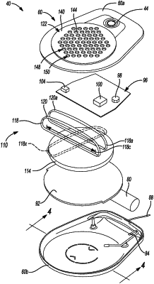
1. A system for transferring thermal energy in a wireless recharger for an implantable system, comprising:
a transmitter coil configured to transmit a power transfer signal when energized by a power source;
a heat spreader member positioned relative to the transmitter coil having a first side and a second side, wherein the heat spreader member includes a plurality of bores formed between the first side and the second side through the heat spreader member;
a diaphragm positioned and moveable relative to the heat spreader member;
a motive member configured to move the diaphragm a selected distance relative to the heat spreader member;
a heat sink having a first side and a second side and configured to absorb thermal energy from near the transmitter coil; and
a heat pipe defining a internal heat pip passage;
wherein a movement of the diaphragm is configured to generate a jet of gas through at least one bore of the plurality of the bores;
wherein the heat pipe includes a first portion positioned to absorb thermal energy from the heat sink and a second portion positioned away from the heat sink;
wherein thermal energy is transformed from the first portion to the second portion.
|