|
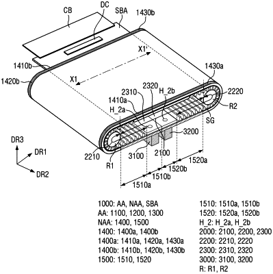
1. A display device, comprising: a display panel including a first active area, a second active area, and a third active area arranged in a first direction, wherein the first active area is disposed between the third active area and the second active area, wherein each of the second active area and the third active area is configured to slide in the first direction, wherein the display panel further includes a dummy first area disposed past the second active area and a second dummy area disposed past the third active area such that each of the first active area, the second active area, and the third active area are disposed between the first dummy area and the second dummy area; a joint part joint part including a plurality of joints, each of the plurality of joints extending in a second direction intersecting the first direction, wherein joints of the plurality of joints are spaced apart from each other in the first direction, wherein the joint part is attached to a bottom surface of the display panel, overlapping the second active area, the third active area, the first dummy area, and the second dummy area; a first fixing tool disposed on the first dummy area of the display panel, the first fixing tool amenable to a sliding behavior of the display panel; and a second fixing tool disposed on the second dummy area of the display panel, the second fixing tool amenable to the sliding behavior of the display panel, wherein the first fixing tool includes a first extension portion extending in the second direction over an entire width of the first dummy area in the second direction and projecting downwards in a third direction perpendicular to the first direction and the second direction, wherein the second fixing tool includes a second extension portion extending in the second direction over an entire width of the second dummy area in the second direction and projecting downwards in the third direction, over the entire width of the second dummy area, and wherein the first extension portion of the first fixing tool is coplanar with the second extension portion of the second fixing tool at both top and bottom surfaces.
|
