| CPC G05D 7/0647 (2013.01) [F16K 1/36 (2013.01); F16K 1/42 (2013.01); F16K 31/0655 (2013.01)] | 17 Claims |

|
1. A valve assembly used to control fluid flow rate, the valve assembly comprising:
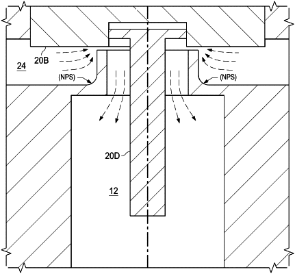
a valve plunger configured to force fluid having a flow rate to flow between an inlet and an outlet in a flow path, the valve plunger having an actuator force applied to a first side of the valve plunger, and the fluid in fluid communication with a second side of the valve plunger, the valve plunger positioned within at least a portion of a flow path perpendicular to an orientation of the valve plunger;
an orifice positioned between the inlet and the outlet, wherein the orifice comprises at least one planar surface and at least one concave surface, the concave surface defined within the portion of the flow path perpendicular to the orientation of the valve plunger,
an actuator configured to apply the actuator force to the first side of the valve plunger, the actuator force being operable to move the valve plunger towards a tubular member forming part of the flow path; and
a shield configured to reduce a destabilizing force that is applied by the fluid to the second side, wherein the shield is a cylindrical protuberance extending from the bottom of the plunger.
|