| CPC G01N 3/307 (2013.01) [G01N 3/02 (2013.01); B62D 25/04 (2013.01); B62D 25/06 (2013.01); G01N 2203/001 (2013.01); G01N 2203/0048 (2013.01); G01N 2203/04 (2013.01)] | 18 Claims |

|
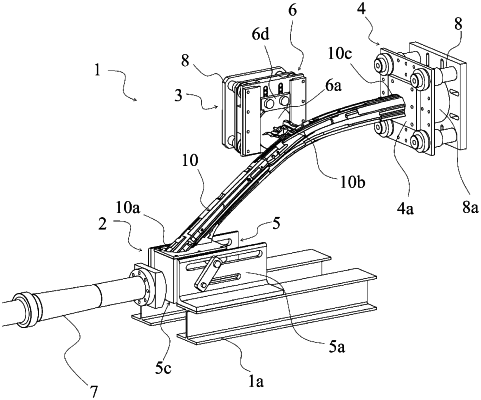
10. A collision performance evaluation test apparatus for an automobile body part that performs an evaluation test of collision performance of an automobile body part,
wherein
the apparatus comprises:
support jigs for supporting a front end portion, an intermediate portion, and a rear end portion of the automobile body part, respectively;
a translation control and rotation control mechanism that is provided in the support jig for supporting the front end portion;
a translation control mechanism that is provided in the support jig for supporting the intermediate portion; and
a collision punch that collides at a test speed with a front surface of an L-shaped plate included in the translation control and rotation control mechanism,
wherein
the translation control and rotation control mechanism includes:
a pair of support members having two rows of horizontal guide grooves parallel to a collision direction;
a rotary box that has an L-shaped plate including an upper surface to which the front end portion of the automobile body part is secured and a front surface with which a collision punch is made to collide and a side surface plate provided on each of both side surfaces of the L-shaped plate, and is held between the support members;
a rotary shaft pin that penetrates, as a rotary shaft of the rotary box, the side surface plate of the rotary box and one of the two rows of horizontal guide grooves;
a first compression pin that penetrates an arcuate guide groove formed about a center axis of the rotary shaft pin as an arc center and provided on the side surface plate of the rotary box and another of the two rows of horizontal guide grooves; and
a connection plate that connects the rotary shaft pin to the first compression pin so that the rotary shaft pin and the first compression pin are rotatable and movable along the horizontal guide grooves, a first energy-absorbing member is disposed inside the arcuate guide groove,
the translation control mechanism includes:
a support plate that is secured to the support jig;
a pair of slide guides that is provided on the support plate;
a disk whose outer circumferential end portion is slidably held between the support plate and the slide guides and that is used to secure the intermediate portion of the automobile body part thereto; and
a translation plate whose both end portions are slidably held between the support plate and the slide guides, respectively, and that is disposed to be in contact with an upper portion of the disk,
a second compression pin that is provided on one of the support plate and the translation plate so as to protrude toward another of the support plate and the translation plate is fitted into a linear guide portion that is formed on the other of the support plate and the translation plate so as to extend in a direction in which the translation plate is slidable and includes a second energy-absorbing member disposed inside,
the first compression pin provided in the translation control and rotation control mechanism is configured to deform the first energy-absorbing member by a rotation of the rotary box about the rotary shaft so as to apply torque opposite to a rotation direction of the rotary box to the rotary box, and
the second compression pin provided in the translation control mechanism is configured to deform the second energy-absorbing member by a translation of the translation plate so as to apply a reaction force in an opposite direction to a translation direction of the translation plate to the translation plate.
|