| CPC G01B 11/03 (2013.01) [G01B 11/2513 (2013.01); G01S 17/89 (2013.01); G01S 17/48 (2013.01)] | 21 Claims |

|
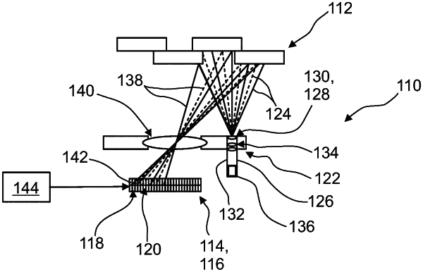
1. A detector (110) for determining a position of at least one object (112), the detector (110) comprising:
at least one projector (122) for illuminating the object (112) with at least two illumination patterns (124), wherein the projector (122) comprises at least one tunable laser source (126) and at least one diffractive optical element (128), wherein the projector (122) is configured to generate the at least two illumination patterns (124) each comprising a plurality of illumination features by controlling at least one property of the tunable laser source (126), wherein the projector (122) comprises at least one control unit (136), wherein the control unit (136) is configured for controlling the at least one property of the tunable laser source (126), wherein the projector (122) is operable in at least two emission modes, wherein the control unit (136) is configured to adjust the emission mode by applying an electrical signal to the tunable laser source (126), wherein in a first emission mode the tunable laser source (126) has a first emission wavelength 21 and in a second emission mode the tunable laser source (126) has a second emission wavelength λ2 different from the first emission wavelength λ1, wherein the at least one projector (122) is configured to project the at least two illumination patterns (124) to at least partly differing locations, wherein the at least one control unit (136) is configured to adjust the emission wavelength in steps or continuously thereby adjusting the location of the at least two illumination patterns (124);
at least one sensor element (114) having a matrix (116) of optical sensors (118), the optical sensors (118) each having a light-sensitive area (120), wherein each optical sensor (118) is designed to generate at least one sensor signal in response to an illumination of its respective light-sensitive area (120) by a reflection light beam propagating from the object (112) to the detector (110), wherein the sensor element (114) is configured to determine at least one reflection image (142); and
at least one evaluation device (144), wherein the evaluation device (144) is configured to select at least one reflection feature of the reflection image (142), wherein the evaluation device (144) is configured for determining at least one longitudinal coordinate z of the selected reflection feature of the reflection image (142) by evaluating a combined signal Q from the sensor signals, wherein the at least one evaluation device is configured for deriving the combined signal Q by
Q(zo)=∫∫A1E(x,y;zo)dxdy/∫∫A2E(x,y;zo)dxdy
wherein x and y are transversal coordinates, A1 and A2 are different areas of at least one beam profile of the reflection light beam at a position of the sensor element, and E(x,y,z0) denotes the beam profile given at the object distance zo, wherein each of the sensor signals comprises at least one information of at least one area of the beam profile of the reflection light beam.
|