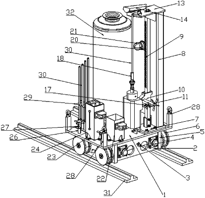
| CPC F27D 25/001 (2013.01) [F27D 3/15 (2013.01)] | 7 Claims |

|
1. An unblocking apparatus for a furnace discharging pipe, comprising a rail detachably mounted below a furnace, characterized in that it further comprises a rail car, an unblocking drive mechanism, a heat-unblocking component, a cold-unblocking component, and a material receiving component, the rail car can move along the rail, the unblocking drive mechanism is arranged on the rail car, the heat-unblocking component and the cold-unblocking component are used to unblock the furnace discharging pipe, a drive end of the unblocking drive mechanism is detachably connected with one end of the heat-unblocking component and the cold-unblocking component respectively, and the material receiving component is used to receive a blocking material in the discharging pipe; the unblocking drive mechanism comprises an upright column, a gear rack, and a gearbox, the gearbox is provided with a dovetail groove mounting bracket, and the dovetail groove mounting bracket can be detachably connected with one end of the heat-unblocking component and the cold-unblocking component;
the heat-unblocking component comprises an adapter apparatus detachably connected with the dovetail groove mounting bracket and an unblocking rod capable of unblocking a viscous blocking material in the discharging pipe, a lower end of the unblocking rod is connected to the adapter apparatus by a quick connector, and the adapter apparatus is provided with a clamping block for easy operation by a mechanical arm;
the cold-unblocking component comprises a drilling machine, a drilling rod, a water collection tank, and a water supply tank, the drilling rod is connected with a drive end of the drilling machine by the quick connector, one end of the drilling machine is detachably connected with the dovetail groove mounting bracket, and the water collection tank and the water supply tank are respectively arranged on a car flat plate by limiting blocks,
the material receiving component is a flow guide groove, upper and lower ends of the upright column are respectively and fixedly connected with an upright column bottom plate and an upright column top plate, the flow guide groove is fixedly connected above the upright column top plate.
|