| CPC F24F 13/12 (2013.01) [F24F 13/20 (2013.01); F24F 2013/1433 (2013.01)] | 16 Claims |

|
1. An indoor unit of an air-conditioning apparatus, comprising:
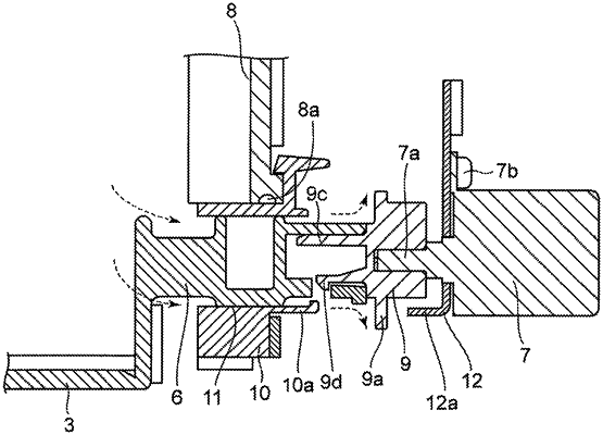
a wind direction vane configured to rotate about a vane shaft to change a flow direction of conditioned air that is blown out from an air outlet provided at an air passage for the conditioned air that is provided in a housing;
a vane motor including a rotary shaft, and configured to drive the wind direction vane to rotate the wind direction vane;
an air passage wall that isolates the air passage from an outside where no conditioned air flows; and
a shaft joint member configured to connect one end portion of the vane shaft and one end portion of the rotary shaft, the vane shaft extending outward from the air passage wall,
wherein an annular gap is provided between the vane shaft and the air passage wall, and
the shaft joint member includes a flange portion between the air passage wall and the vane motor, and the flange portion radially extends outward from a center, the shaft joint member includes a fitted shaft portion that extends axially with respect to a center axis of the rotary shaft and spaces the flange portion apart from the annular gap along a length of the fitted shaft portion, thereby causing air that flows toward the vane motor after exiting the annular gap to continue to flow axially along the vane shaft and then be diffused by the flange portion outward relative to a direction toward the vane motor, and
the flange portion is circular with respect to the center axis of the vane shaft and the rotary shaft.
|