| CPC F17C 3/08 (2013.01) [F17C 3/10 (2013.01); F17C 2221/017 (2013.01); F17C 2223/0161 (2013.01); F17C 2250/0443 (2013.01)] | 8 Claims |

|
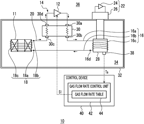
1. A cryogenic cooling system comprising:
a gas circulation source that circulates a cooling gas;
a cryocooler including a cryocooler stage that cools the cooling gas;
an object-to-be-cooled gas flow path provided around or inside an object to be cooled for causing the cooling gas to flow therethrough;
a gas supply line that connects the gas circulation source to an inlet of the object-to-be-cooled gas flow path to supply the cooling gas from the gas circulation source via the cryocooler stage to the object-to-be-cooled gas flow path;
a gas recovery line that connects an outlet of the object-to-be-cooled gas flow path to the gas circulation source so as to recover the cooling gas from the object-to-be-cooled gas flow path to the gas circulation source;
at least one temperature sensor that is installed at a measurement location away from the inlet of the object-to-be-cooled gas flow path along the gas supply line and/or a measurement location installed away from the outlet of the object-to-be-cooled gas flow path along the gas recovery line; and
a gas flow rate control unit that controls the gas circulation source so as to adjust a flow rate of the cooling gas flowing through the object-to-be-cooled gas flow path in accordance with a measured temperature at at least one measurement location by the temperature sensor,
wherein the gas flow rate control unit includes a gas flow rate table configured to associate a target cooling gas flow rate with each of a plurality of different cooling temperatures at a specific measurement location, and
wherein the gas flow rate control unit determines the target cooling gas flow rate in accordance with a measured temperature at the specific measurement location according to the gas flow rate table, and controls the gas circulation source so as to cause the cooling gas to flow through the object-to-be-cooled gas flow path with the target cooling gas flow rate.
|