| CPC F16L 25/12 (2013.01) [F16L 21/06 (2013.01); F16L 59/024 (2013.01); F16L 17/04 (2013.01); F16L 55/17 (2013.01); Y10T 29/49826 (2015.01)] | 9 Claims |

|
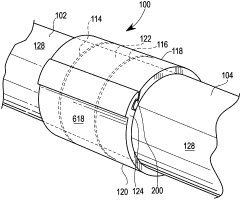
1. A device for forming a tubular coupling, comprising:
a fitting section having a longitudinal length and a generally half-tubular cross-section having a thickness and an inside radius, the fitting section further comprising:
a first end of the cross-section having a receiving shape having a length, the receiving shape having an interior surface having the inside radius for the entire length of the receiving shape, and an exterior surface including a receiving shape locking face at a receiving distance from a terminus of the first end, wherein the interior surface and the exterior surface define a thickness of the receiving shape, wherein the receiving shape locking face comprises a first portion proximate to the terminus of the first end and a second portion contiguous with the first portion, wherein the second portion has a thickness less than the thickness of the first portion and the thickness of the second portion is at least 50% of the fitting section thickness; and
a second end of the cross-section having a locking shape, the locking shape having a portion of an interior surface of the locking shape located outwards of the inside radius, thereby forming a notch in the interior surface of the locking shape, the locking flange notch including:
a distal locking face located at a first distance from a terminus of the second end; and
a proximate locking face located between the distal locking face and the terminus of the second end, whereby the notch has a width between the proximate locking face and the distal locking face, wherein the width of the notch is nominally equal to the receiving distance of the receiving shape; wherein
the notch is configured to fit over and couple to a receiving shape of a second fitting section having the same geometry as the fitting section, including the receiving shape locking face of the second fitting section juxtaposed with the proximate locking face and the terminus of the first end of the second fitting section being located within the notch; and wherein
the receiving shape is configured to receive and couple to a locking shape of the second fitting section including the receiving shape locking face juxtaposed with a proximate locking face of the second fitting section and the terminus of the first end being located within a notch of the second fitting section, whereby coupling of the fitting section to the second fitting section forms the tubular coupling, said tubular coupling having the inside radius.
|