| CPC F16J 15/3268 (2013.01) [F16J 15/3284 (2013.01)] | 15 Claims |

|
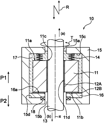
1. A seal structure for sealing a gap between an opening provided in a housing and a shaft member inserted through the opening, comprising:
a bush provided between the shaft member and the housing and arranged around the shaft member, the bush being tubular and relatively movable with respect to the shaft member in an axial direction and/or a circumferential direction;
a pressure-receiving member having a facing surface facing an end surface of the bush on one side in the axial direction; and
an elastic member that presses the bush against the pressure-receiving member from another side in the axial direction,
wherein:
a first coating layer is provided between an outer peripheral surface of the shaft member and an inner peripheral surface of a shaft hole of the bush, wherein the inner peripheral surface of the shaft hole is a surface of the bush that is radially closest to the shaft member, the outer peripheral surface of the shaft member comprises a first portion superimposed in a radial direction with the inner peripheral surface of the shaft hole, and at least a part of the first coating layer is provided between the first portion and the inner peripheral surface of the shaft hole, and
a second coating layer is formed between an end surface of the bush on the one side in the axial direction and the facing surface of the pressure-receiving member, wherein the end surface of the bush on the one side in the axial direction comprises a second portion superimposed in the axial direction with the facing surface of the pressure-receiving member, and at least a part of the second coating layer is provided between the second portion and the facing surface of the pressure-receiving member.
|