| CPC F16C 33/7853 (2013.01) [B60G 15/068 (2013.01); F16C 33/7833 (2013.01); B60G 2202/31 (2013.01); B60G 2204/418 (2013.01); F16C 2326/05 (2013.01)] | 4 Claims |

|
1. A strut bearing device comprising:
an uppercase;
a lower case;
an upper raceway ring held by the upper case;
a lower raceway ring held by the lower case;
a rolling element that rolls between the upper raceway ring and the lower raceway ring; and
a seal positioned in at least one of a radially inner side of the rolling element and a radially outer side of the rolling element, wherein
the upper case and the lower case are made of a synthetic resin,
the seal is made of elastomer,
the seal has an annular base and a seal lip projecting from the annular base,
the annular base has an axially end face from which no seal lip projects, the axially end face being in contact with an annular joint surface of the upper case or an annular joint surface of the lower case,
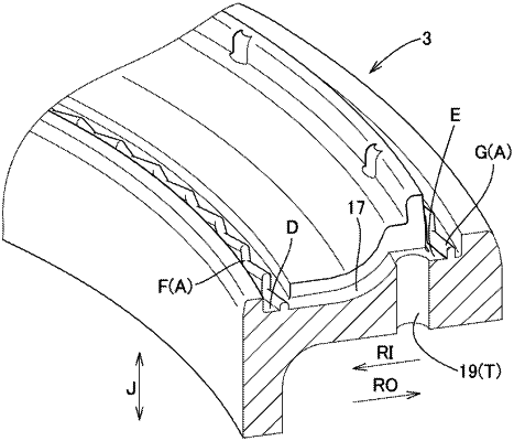
the annular joint surface has one of a case-side projection projecting in an axial direction and a case-side recess dented in the axial direction,
each of the case-side projection and the case-side recess has a shape seen in the axial direction, the shape continuing in a circumferential direction and varying a position of the shape in a radial direction along the circumferential direction, and
the seal has one of a seal-side recess having a shape that is fitted to the case-side projection, and a seal-side projection having a shape that is fitted in the case-side recess.
|
|
3. A method of producing a lower case and a seal which are included in a strut bearing device,
wherein
the seal is positioned in at least one of a radially inner side of a rolling element of the strut bearing device and a radially outer side of the rolling element,
the lower case is made of a synthetic resin,
the seal is made of elastomer,
the seal has an annular base and a seal lip projecting from the annular base,
the annular base has an axially end face from which no seal lip projects, the axially end face being in contact with an annular joint surface of the lower case,
the annular joint surface of the lower case has one of a case-side projection projecting in an axial direction and a case-side recess dented in the axial direction,
each of the case-side projection and the case-side recess, of the lower case, has a shape seen in the axial direction, the shape continuing in a circumferential direction and varying a position of the shape in a radial direction along the circumferential direction,
the method comprising:
an injection molding step of injecting the synthetic resin that is melted, from a gate of a first molding die for molding the lower case having the shape, and
an insert injection molding step of injecting the elastomer that is melted, from a gate of a second molding die, in a state where the lower case removed from the first molding die is placed, as an insert work, in the second molding die for molding the seal having the shape.
|
|
4. A method of producing an upper case and a seal which are included in a strut bearing device,
wherein
the seal is positioned in at least one of a radially inner side of a rolling element of the strut bearing device and a radially outer side of the rolling element,
the upper case is made of a synthetic resin,
the seal is made of elastomer,
the seal has an annular base and a seal lip projecting from the annular base,
the annular base has an axially end face from which no seal lip projects, the axially end face being in contact with an annular joint surface of the upper case,
the annular joint surface of the upper case has one of a case-side projection projecting in an axial direction and a case-side recess dented in the axial direction,
each of the case-side projection and the case-side recess, of the upper case, has a shape seen in the axial direction, the shape continuing in a circumferential direction, and varying a position of the shape in a radial direction along the circumferential direction,
the method comprising:
an injection molding step of injecting the synthetic resin that is melted, from a gate of a first molding die for molding the upper case having the shape, and
an insert injection molding step of injecting the elastomer that is melted from a gate of a second molding die in a state where the upper case removed from the first molding die is placed, as an insert work, in the second molding die for molding the seal having the shape.
|